Sign In
Upload
Manuals
Brands
Siemens Manuals
Protection Device
SIPROTEC 7UM62
Siemens SIPROTEC 7UM62 Manuals
Manuals and User Guides for Siemens SIPROTEC 7UM62. We have
3
Siemens SIPROTEC 7UM62 manuals available for free PDF download: Manual
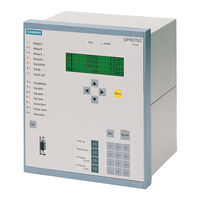
Siemens SIPROTEC 7UM62 Manual (638 pages)
Multifunctional Machine Protection
Brand:
Siemens
| Category:
Protection Device
| Size: 12.96 MB
Table of Contents
Table of Contents
9
Introduction
21
Overall Operation
22
Application Scope
25
Characteristics
27
Functions
35
Introduction, Reference Power System
37
Function Description
37
Device
39
Setting Notes
39
Settings
40
Information List
41
Ethernet EN100 Modul
42
Function Description
42
Setting Notes
42
Information List
42
Functional Scope
43
Functional Description
43
Setting Notes
44
Settings
48
Power System Data 1
53
Setting Notes
53
Settings
60
Information List
61
Change Group
62
Setting Notes
62
Settings
62
Information List
62
Power System Data 2
63
Function Description
63
Setting Notes
63
Settings
63
Information List
64
Definite-Time Overcurrent Protection (I>, ANSI 50/51) with Undervoltage Seal-In
65
Function Description
65
Setting Notes
66
Settings
68
Information List
68
Definite-Time Overcurrent Protection (I>>, ANSI 50, 51, 67) with Direction Detection
69
Function Description
69
Setting Notes
72
Settings
74
Information List
74
Inverse-Time Overcurrent Protection (ANSI 51V)
75
Function Description
75
Setting Notes
79
Settings
80
Information List
80
Thermal Overload Protection (ANSI 49)
81
Function Description
81
Setting Notes
85
Settings
89
Information List
90
Unbalanced Load (Negative Sequence) Protection (ANSI 46)
91
Function Description
91
Setting Notes
94
Settings
97
Information List
97
Startup Overcurrent Protection (ANSI 51)
98
Function Description
98
Setting Notes
99
Settings
101
Information List
101
Differential Protection and Its Protected Objects
102
Differential Protection (ANSI 87G/87M/87T)
102
Function Description
102
Setting Notes
112
Settings
112
Information List
113
Protected Object Generator or Motor
115
Function Description
115
Setting Notes
116
Protected Object Transformer
118
Function Description
118
Setting Notes
122
Current Transformer Requirements
126
Function Description
126
Earth Current Differential Protection (ANSI 87GN,TN)
128
Function Description
128
Setting Notes
133
Settings
135
Information List
135
Underexcitation (Loss-Of-Field) Protection (ANSI 40)
136
Function Description
136
Setting Notes
139
Settings
143
Information List
144
Reverse Power Protection (ANSI 32R)
145
Functional Description
145
Setting Notes
146
Settings
148
Information List
148
Forward Active Power Supervision (ANSI 32F)
149
Functional Description
149
Setting Notes
150
Settings
151
Information List
151
Impedance Protection (ANSI 21)
152
Functional Description
152
Power Swing Blocking
157
Setting Notes
158
Settings
163
Information List
164
Out-Of-Step Protection (ANSI 78)
165
Measuring Principle
165
Out-Of-Step Protection Logic
167
Setting Notes
169
Settings
174
Information List
174
Undervoltage Protection (ANSI 27)
175
Functional Description
175
Setting Notes
176
Settings
177
Information List
177
Overvoltage Protection (ANSI 59)
178
Functional Description
178
Setting Notes
179
Settings
180
Information List
180
Frequency Protection (ANSI 81)
181
Functional Description
181
Setting Notes
182
Settings
183
Information List
184
Overexcitation (Volt/Hertz) Protection (ANSI 24)
185
Functional Description
185
Setting Notes
187
Settings
189
Information List
189
Inverse-Time Undervoltage Protection (ANSI 27)
190
Function Description
190
Setting Notes
191
Settings
192
Information List
192
Rate-Of-Frequency-Change Protection Df/Dt (ANSI 81R)
193
Function Description
193
Setting Notes
195
Settings
197
Information List
198
Jump of Voltage Vector
199
Functional Description
199
Setting Notes
201
Settings
202
Information List
202
Stator Earth Fault Protection (ANSI 59N, 64G, 67G)
203
Functional Description
203
Setting Notes
208
Settings
210
Information List
210
Sensitive Earth Fault Protection (ANSI 51GN, 64R)
211
Functional Description
211
Setting Notes
213
Settings
214
Information List
214
Stator Earth Fault Protection with 3Rd Harmonics (ANSI 27/59TN 3Rd Harm.)
215
Functional Description
215
Setting Notes
219
Settings
222
Information List
222
Stator Earth Fault Protection with 20 Hz Voltage Injection (ANSI 64G - 100%)
223
Function Description
223
Setting Notes
226
Settings
230
Information List
230
Sensitive Earth Fault Protection B (ANSI 51GN)
231
Function Description
231
Setting Notes
234
Settings
235
Information List
235
Interturn Protection (ANSI 59N (IT))
236
Functional Description
236
Setting Notes
238
Settings
239
Information List
239
Rotor Earth Fault Protection R, Fn (ANSI 64R)
240
Function Description
240
Setting Notes
242
Settings
244
Information List
244
Sensitive Rotor Earth Fault Protection with 1 to 3 Hz Square Wave Voltage Injection (ANSI 64R - 1 to 3 Hz)
245
Function Description
245
Setting Notes
249
Settings
250
Information List
250
Motor Starting Time Supervision (ANSI 48)
251
Functional Description
251
Setting Notes
253
Settings
254
Information List
254
Restart Inhibit for Motors (ANSI 66, 49Rotor)
255
Functional Description
255
Setting Notes
259
Settings
262
Information List
262
Breaker Failure Protection (ANSI 50BF)
263
Function Description
263
Setting Notes
266
Settings
267
Information List
267
Inadvertent Energization (ANSI 50, 27)
268
Functional Description
268
Setting Notes
269
Settings
270
Information List
270
DC Voltage/Current Protection (ANSI 59NDC/51NDC)
271
Functional Description
271
Setting Notes
273
Settings
274
Information List
274
Analog Outputs
275
Function Description
275
Setting Notes
277
Settings
281
Monitoring Functions
282
Measurement Supervision
282
Hardware Monitoring
282
Software Monitoring
284
Monitoring of External Transformer Circuits
285
Setting Notes
287
Settings
287
Information List
288
Supervision
289
Fuse Failure Monitor
289
Malfunction Responses of the Monitoring Functions
291
Setting Notes
293
Settings
293
Information List
294
Trip Circuit Supervision
295
Functional Description
295
Setting Notes
299
Settings
301
Information List
301
Threshold Supervision
302
Functional Description
302
Setting Notes
306
Settings
306
Information List
312
External Trip Functions
313
Functional Description
313
Setting Notes
313
Settings
313
Information List
315
Temperature Detection by Thermoboxes
316
Function Description
316
Setting Notes
317
Settings
319
Information List
324
Phase Rotation
325
Functional Description
325
Setting Notes
326
Protection Function Control
327
Pickup Logic for the Entire Device
327
Function Description
327
Tripping Logic for the Entire Device
328
Functional Description
328
Setting Notes
328
Auxiliary Functions
329
Processing of Annunciation
329
Function Description
329
Statistics
331
Functional Description
331
Information List
332
Measurement (Secondary/Primary/Percentage Values)
333
Functional Description
333
Information List
337
Thermal Measurement
338
Description
338
Information List
339
Diff- and Rest. Measurement
340
Information List
340
Min/Max Measurement Setup
341
Information List
341
Energy
342
Information List
342
Set Points (Measured Values)
343
Information List
343
Set Points (Statistic)
343
Oscillographic Fault Records
344
Function Description
344
Setting Notes
344
Settings
345
Information List
345
Date and Time Stamping
346
Functional Description
346
Commissioning Aids
347
Test Messages to the SCADA Interface During Test Operation
347
Checking the System Interface
347
Checking the Binary Inputs and Outputs
348
Creating a Test Fault Record
348
Command Processing
349
Control Device
349
Description
349
Types of Commands
350
Description
350
Command Processing
351
Description
351
Interlocking
352
Description
352
Command Logging
359
Description
359
Mounting and Commissioning
361
Mounting and Connections
362
Configuration Information
362
Hardware Modifications
365
General
365
Disassembly
367
Switching Elements on the Printed Circuit Boards
370
Interface Modules
383
Reassembly
386
Mounting
386
Panel Flush Mounting
386
Rack and Cubicle Mounting
388
Panel Surface Mounting
389
Checking Connections
390
Checking Data Connections of Interfaces
390
System Interface
391
Termination
391
Analog Output
392
Time Synchronization Interface
392
Optical Fibres
393
Checking the Device Connections
393
Checking System Incorporation
397
Commissioning
400
Test Mode / Transmission Block
401
Testing System Interfaces
401
Checking the Binary Inputs and Outputs
403
Tests for Circuit Breaker Failure Protection
406
Testing Analog Output
406
Testing User-Defined Functions
406
Checking the Rotor Ground Fault Protection at Standstill
407
Checking the 100 % Stator Earth Fault Protection
411
Checking the DC Voltage / DC Current Circuit
414
Trip/Close Tests for the Configured Operating Devices
414
Commissioning Test with the Machine
414
Checking the Current Circuits
419
Checking the Differential Protection
421
Checking the Earth Current Differential Protection
424
Checking the Voltage Circuits
428
Checking the Stator Ground Fault Protection
430
Checking the 100 % Stator Ground Fault Protection
438
Checking the Sensitive Ground Fault Protection as Rotor Ground Fault Protection
439
Checking the Rotor Ground Fault Protection During Operation
440
Checking the Interturn Fault Protection
441
Checks with the Network
443
Creating Oscillographic Fault Recordings for Tests
447
Final Preparation of the Device
449
Technical Data
451
General
453
Analog Inputs/Outputs
453
Auxiliary Voltage
454
Binary Inputs and Outputs
455
Communication Interfaces
457
Electrical Tests
461
Mechanical Stress Tests
462
Climatic Stress Tests
463
Service Conditions
464
Certifications
464
Design
464
Definite-Time Overcurrent Protection (ANSI 50, 51 67)
465
Inverse-Time Overcurrent Protection (ANSI 51V)
466
Thermal Overload Protection (ANSI 49)
471
Unbalanced Load (Negative Sequence) Protection (ANSI 46)
473
Startup Overcurrent Protection (ANSI 51)
475
Differential Protection (ANSI 87G/87M/87T) for Generators and Motors
476
Differential Protection (ANSI 87G/87M/87T) for Transformers
478
Earth Current Differential Protection (ANSI 87GN,TN)
481
Underexcitation (Loss-Of-Field) Protection (ANSI 40)
482
Reverse Power Protection (ANSI 32R)
483
Forward Active Power Supervision (ANSI 32F)
484
Impedance Protection (ANSI 21)
485
Out-Of-Step Protection (ANSI 78)
487
Undervoltage Protection (ANSI 27)
488
Overvoltage Protection (ANSI 59)
490
Frequency Protection (ANSI 81)
491
Overexcitation (Volt/Hertz) Protection (ANSI 24)
492
Rate-Of-Frequency-Change Protection Df/Dt (ANSI 81R)
494
Jump of Voltage Vector
495
Stator Earth Fault Protection (ANSI 59N, 64G, 67G)
496
Sensitive Earth Fault Protection (ANSI 51GN, 64R)
497
Stator Earth Fault Protection with 3Rd Harmonics (ANSI 27/59TN 3Rd Harm.)
498
Stator Earth Fault Protection with 20 Hz Voltage Injection (ANSI 64G - 100%)
499
Sensitive Earth Fault Protection B (ANSI 51GN)
500
Interturn Protection (ANSI 59N (IT))
501
Rotor Earth Fault Protection R, Fn (ANSI 64R)
502
Sensitive Rotor Earth Fault Protection with 1 to 3 Hz Square Wave Voltage Injection (ANSI 64R - 1 to 3 Hz)
504
Motor Starting Time Supervision (ANSI 48)
505
Restart Inhibit for Motors (ANSI 66, 49Rotor)
506
Breaker Failure Protection (ANSI 50BF)
507
Inadvertent Energization (ANSI 50, 27)
508
DC Voltage/Current Protection (ANSI 59NDC/51NDC)
509
Temperature Detection by Thermoboxes
510
Threshold Supervision
511
User-Defined Functions (CFC)
512
Additional Functions
517
Operating Range of the Protection Functions
523
Dimensions
525
Panel Flush and Cubicle Mounting (Housing Size 1 / 2 )
525
Housing for Panel Flush Mounting or Cubicle Mounting (Size )
526
Panel Flush Mounting (Housing Size )
527
Housing for Panel Surface Mounting (Size )
527
Dimensional Drawing of Coupling Device 7XR6100-0CA0 for Panel Flush Mounting
528
Dimensions of Coupling Unit 7XR6100-0BA0 for Panel Surface Mounting
529
Dimensional Drawing of 3PP13
530
Dimensional Drawing of Series Device 7XT7100-0BA00 for Panel Surface Mounting
531
Dimensions of Series Unit 7XT7100-0EA00 for Panel Flash Mounting
532
Dimensional Drawing of Resistor Unit 7XR6004-0CA00 for Panel Surface Mounting or Cubicle Flush Mounting
533
Dimensions of Resistor Unit 7XR6004-0BA00 for Panel Surface Mounting
534
Dimensional Drawing of 20 Hz Generator 7XT3300-0CA00 for Panel Surface Mounting or Cubicle Flush Mounting
535
Maßbild 20 Hz-Generator 7XT3300-0CA00/DD für Schalttafel- oder Schrankeinbau
536
Dimensional Drawing of 20 Hz Generator 7XT3300-0BA00 for Panel Surface Mounting
537
Maßbild 20 Hz-Generator 7XT3300-0BA00/DD für Schalttafelaufbau
538
Dimensional Drawing of 20 Hz Bandpass 7XT3400-0CA00 for Panel Surface Mounting or Cubicle Flush Mounting
539
Dimensional Drawing of 20 Hz Bandpass 7XT3400-0BA00 for Panel Surface Mounting
540
Appendix
541
Ordering Information and Accessories
542
Ordering Information
542
Order Key
542
Accessories
546
Terminal Assignments
549
Panel Flush Mounting or Cubicle Mounting
549
Panel Surface Mounting
551
Connection Examples
553
7UM62 - Connection Examples
553
Connection Examples for RTD Box
561
Schematic Diagram of Accessories
562
Default Settings
565
Leds
565
Binary Input
566
Binary Output
566
Function Keys
567
Default Display
568
Pre-Defined CFC Charts
569
Advertisement
Siemens SIPROTEC 7UM62 Manual (602 pages)
Multifunction Generator, Motor and Transformer Protection Relay
Brand:
Siemens
| Category:
Relays
| Size: 9.19 MB
Table of Contents
Table of Contents
7
1 Introduction
17
Overall Operation
18
C53000-G1176-C149
19
Applications
21
Features
23
2 Functions
29
Introduction, Reference Power System
32
Functional Scope
34
Description
34
Setting Hints
34
Settings
39
Power System Data 1
43
Functional Description
43
Setting Hints
43
Settings 1
49
List of Information
50
Setting Groups
51
Functional Description
51
Setting Hints
51
Settings
51
Information
51
Power System Data 2
52
Functional Description
52
Setting Hints
52
Settings
52
Information
52
Definite-Time Overcurrent Protection (I>, ANSI 50/51) with Undervoltage Seal-In38
54
Functional Description
54
Setting Hints
55
Settings for the Definite-Time Overcurrent Protection (Stage I>)
56
Information from Definite-Time Overcurrent Protection (Stage I>)
57
Definite-Time Overcurrent Protection (I>>, ANSI 50, 51, 67) with Direction Detection
58
Functional Description
58
Setting Hints
60
Settings for the I>> Stage of the Definite-Time Overcurrent Protection
63
Information for the I>> Stage of the Definite-Time Overcurrent Protection
63
Inverse-Time Overcurrent Protection (ANSI 51V)
64
Functional Description
64
Setting Hints
68
Settings of the Inverse O/C Time Protection
69
Information for the Inverse-Time Overcurrent Protection
70
Thermal Overload Protection (ANSI 49)
71
Functional Description
71
Setting Hints
75
Thermal Overload Protection Settings
79
Information List for the Thermal Overload Protection
80
Unbalanced Load (Negative Sequence) Protection (ANSI 46)
81
Functional Description
81
Setting Hints
83
Settings of the Unbalanced Load Protection
85
Information for the Unbalanced Load Protection
86
Startup Overcurrent Protection (ANSI 51)
87
Functional Description
88
Setting Hints
88
Settings of the Startup Overcurrent Protection
90
Information for the Startup Overcurrent Protection
90
Differential Protection (ANSI 87G/87M/87T)
91
Functional Description
91
Protected Object Generator or Motor: Particularities
93
Protected Object Transformer: Particularities
94
Evaluation of Measured Quantities
97
Setting Hints
105
Differential Protection for Generators and Motors
105
Differential Protection for Transformers
107
Settings of the Differential Protection
111
Information for the Differential Protection
112
Earth Current Differential Protection (ANSI 87GN, TN)
114
Functional Description
114
Setting Hints
119
Settings of the Earth Current Differential Protection
121
Information for the Earth Current Differential Protection
121
Underexcitation (Loss-Of-Field) Protection (ANSI 40)
122
Functional Description
122
Setting Hints
125
Settings of the Underexcitation (Loss-Of-Field) Protection
129
Information for the Underexcitation (Loss-Of-Field) Protection
130
Reverse Power Protection (ANSI 32R)
131
Functional Description
131
Setting Hints
132
Settings of the Reverse Power Protection
133
Information for the Reverse Power Protection
134
Forward Active Power Supervision (ANSI 32F)
135
Functional Description
135
Setting Hints
136
Settings of the Forward Active Power Supervision
136
Information for the Forward Power Supervision
137
Impedance Protection (ANSI 21)
138
Functional Description
138
Pickup
138
Determination of the Short-Circuit Impedance
139
Tripping Characteristic
141
Tripping Logic
142
Setting Hints
144
Power Swing Blocking
147
Setting Hints
148
Settings of the Impedance Protection
151
Information from the Impedance Protection
151
Out-Of-Step Protection (ANSI 78)
153
Functional Description
153
Measuring Principle
153
Out-Of-Step Logic
155
Setting Hints
158
Settings of the Out-Of-Step Protection
162
Information for the Out-Of-Step Protection
163
Undervoltage Protection (ANSI 27)
164
Functional Description
164
Setting Hints
165
Settings of the Undervoltage Protection
166
Information for the Undervoltage Protection
166
Overvoltage Protection (ANSI 59)
167
Functional Description
167
Setting Hints
167
Settings of the Overvoltage Protection
168
Information for the Overvoltage Protection
168
Frequency Protection (ANSI 81)
170
Functional Description
170
Setting Hints
171
Settings for the Frequency Protection
173
Information for Frequency Protection
173
Overexcitation (Volt/Hertz) Protection (ANSI 24)
175
Functional Description
175
Setting Hints
177
Settings of the Overexcitation Protection
179
Information from the Overexcitation Protection
179
Inverse-Time Undervoltage Protection (ANSI 27)
180
Functional Description
180
Setting Hints
181
Settings of the Inverse Undervoltage Protection
182
Information for the Inverse Undervoltage Protection
182
Rate-Of-Frequency-Change Protection Df/Dt (ANSI 81R)
183
Functional Description
183
Setting Hints
184
Settings of the Rate-Of-Frequency-Change Protection
186
Information for the Rate-Of-Frequency-Change Protection
187
Jump of Voltage Vector
188
Functional Description
189
Setting Hints
190
Settings of the Vector Jump Detection
191
Information for the Vector Jump Detection
192
Stator Earth Fault Protection (ANSI 59N, 64G, 67G)
193
Functional Description
193
Setting Hints
197
Settings of the 90% Stator Earth Fault Protection
199
Information for the 90% Stator Earth Fault Protection
200
Sensitive Earth Fault Protection (ANSI 51GN, 64R)
201
Functional Description
201
Setting Hints
203
Settings of the Sensitive Earth Fault Protection
204
Information for the Sensitive Earth Current Detection
204
Stator Earth Fault Protection with 3Rd Harmonics (ANSI 27/59TN 3Rd Harm.)
205
Functional Description
205
Setting Hints
207
Settings of the 100-%-Stator Earth Fault Protection with 3Rd Harmonics
208
Information for the 100-% Stator Earth Fault Protection with 3Rd Harmonics
209
Stator Earth Fault Protection with 20 Hz Voltage Injection (ANSI 64G - 100%)
210
Functional Description
210
Setting Hints
213
Settings of the 100-% Stator Earth Fault Protection
215
Information for the 100-% Stator Earth Fault Protection
216
Rotor Earth Fault Protection R, Fn (ANSI 64R)
217
Functional Description
217
Setting Hints
219
Settings of the Rotor Earth Fault Protection
220
Information for the Rotor Earth Fault Protection
221
Sensitive Rotor Earth Fault Protection with 1 to 3 Hz Square Wave Voltage Injection (ANSI 64R - 1 to 3 Hz)
222
Functional Description
222
Setting Hints
227
Settings of the Sensitive Rotor Earth Fault Protection
228
Information for the Sensitive Earth Fault Protection
228
Motor Starting Time Supervision (ANSI 48)
229
Functional Description
229
Setting Hints
231
Settings of the Motor Starting Time Supervision
232
Information for the Motor Starting Time Supervision
232
Restart Inhibit for Motors (ANSI 66, 49Rotor)
233
Functional Description
233
Setting Hints
236
Settings of the Restart Inhibit for Motors
239
Information for the Motor Restart Inhibit
240
Breaker Failure Protection (ANSI 50BF)
241
Functional Description
241
Setting Hints
243
Settings for Breaker Failure Protection
244
Information for the Breaker Failure Protection
245
Inadvertent Energization (ANSI 50, 27)
246
Functional Description
246
Setting Hints
247
Settings of the Inadvertent Energizing Protection
248
Information for the Inadvertent Energizing Function
248
DC Voltage/DC Current Protection (ANSI 59NDC/51NDC)
250
Functional Description
250
Setting Hints
252
Settings of the DC Voltage Protection
254
Information from the DC Voltage Protection
254
Analog Outputs
255
Functional Description
255
Setting Hints
255
Settings of the Analog Outputs
256
Measured Value Monitoring Functions
257
Functional Description
257
Hardware Monitoring
257
Software Monitoring
259
Monitoring of External Current Transformer Circuits
259
Fuse Failure Monitoring
261
Malfunction Responses of the Monitoring Functions
263
Setting Hints
265
Settings
266
Information of the Monitoring Functions
267
Sum Events of the Monitoring Functions
268
Trip Circuit Supervision
270
Functional Description
270
Setting Hints
274
Settings for the Trip Circuit Supervision
276
Information
276
Threshold Supervision
277
Functional Description
277
Setting Hints
279
Settings of the Threshold Supervision
280
Information for the Threshold Supervision
282
External Trip Coupling
283
Functional Description
283
Setting Hints
283
Settings
284
Information for the Function Control
284
Temperature Detection by Thermoboxes
286
Functional Description
286
Setting Hints
287
Settings of the Temperature Detection Function
289
Information for the Temperature Detection Function
293
Inversion of Phase Sequence (Phase Sequence Reversal)
295
Functional Description
295
Setting Hint
296
Protection Function Logic
297
Functional Description
297
Processing Tripping Logic
297
Processing Tripping Logic
298
Functional Description
298
Settings for the Tripping Logic
299
Fault Display on the Leds/Lcd
299
Principle of Function
299
Settings
299
Statistical Counters
300
Functional Description
300
Setting/Resetting
300
Information for the Statistical Counter
301
Auxiliary Functions
302
Processing of Messages
302
Operational Annunciations
303
Fault Annunciations
303
General Interrogation
304
Spontaneous Annunciations
304
Statistical Counters
304
Measurements
305
Oscillographic Fault Recording (Waveform Capture)
308
Date and Time Stamping
309
Commissioning Aids
310
Influencing Information on the System Interface During Test Operation
310
Testing the System Interface
310
Testing the States of the Binary Inputs/Outputs
311
Creating a Test Oscillographic Recording
311
Setting Hints
311
Settings for Oscillographic Fault Recording
312
Information for the Oscillographic Fault Recording
312
Information for Minimum and Maximum Values
313
Breaker Control
314
Types of Commands
315
Steps in the Command Sequence
315
Interlocking
316
Interlocked / Non-Interlocked Switching
317
Recording and Acknowledgement of Commands
324
3 Installation and Commissioning
325
Installation and Connections
326
Installation
326
Connections
330
Hardware Modifications
332
General
332
Disassembling the Device
334
Switching Elements on Printed Circuit Boards
337
Interface Modules
348
To Reassemble the Device
351
Checking Connections and System (Plant) Integration
352
Checking the Data Connections of Serial Interfaces
352
Checking the Device Connections
354
Checking the Integration in the Plant
359
General Hints
359
Commissioning
362
Test Mode and Blocking Data Transmission
363
Testing the System Interface
363
Checking the Binary Inputs and Outputs
365
Testing the Breaker Failure Scheme
367
Checking the Analog Outputs
368
Testing User-Defined Functions (CFC)
368
Checking the Rotor Earth Fault Protection at Stand-Still
368
Rotor Earth Fault Protection (R, Fn)
368
Rotor Earth Fault Protection (1 to 3 Hz)
370
Checking the 100-% Stator Earth Fault Protection
372
Checking the DC Voltage/DC Current Circuit
374
Trip/Close Tests for Primary Equipment
375
Primary Commissioning Tests with the Generator
376
General Hints
376
Checking the Current Circuits
380
Checking the Differential Protection
382
Checking the Earth Current Differential Protection
384
Checking the Voltage Circuits
389
Checking the Stator Earth Fault Protection
390
Unit Connection
391
Busbar Connection
394
Testing the 100-% Stator Earth Fault Protection
398
Checking the Sensitive Earth Fault Protection When Used for Rotor Earth Fault Protection
400
Checking the Rotor Earth Fault Protection During Operation
400
Rotor Earth Fault Protection (R, Fn)
400
Rotor Earth Fault Protection (1 to 3 Hz)
401
Tests with the Generator Connected to the Network
402
Checking the Correct Connection Polarity
402
Measurement of Motoring Power (Reverse Power) and Angle Error Correction
402
Calibrating the Reverse Power Protection
403
Checking the Underexcitation Protection
404
Checking the Directional Function of the Overcurrent Time Protection
405
Triggering Oscillographic Recordings
405
Final Preparation of the Device
407
4 Technical Data
409
General Device Data
411
Analog Inputs
411
Power Supply
412
Binary Inputs and Outputs
412
Communications Interfaces
413
Electrical Tests
417
Mechanical Stress Tests
419
Climatic Stress Tests
419
Service Conditions
420
Certifications
420
Construction
421
Definite-Time Overcurrent Protection (ANSI 50, 67)
422
Inverse-Time Overcurrent Protection (ANSI 51, 67)
423
Thermal Overload Protection (ANSI 49)
428
Unbalanced Load (Negative Sequence) Protection (ANSI 46)
430
Startup Overcurrent Protection (ANSI 51)
432
Differential Protection for Generators and Motors (ANSI 87G/87M)
433
Differential Protection for Transformers (ANSI 87T)
435
Earth Current Differential Protection (ANSI 87GN/TN)
438
Underexcitation (Loss-Of-Field) Protection (ANSI 40)
439
Reverse Power Protection (ANSI 32R)
440
Forward Power Supervision (ANSI 32F)
441
Impedance Protection (ANSI 21)
442
Out-Of-Step Protection (ANSI 78)
443
Undervoltage Protection (ANSI 27)
444
Overvoltage Protection (ANSI 59)
446
Frequency Protection (ANSI 81)
447
Overexcitation (Volt/Hertz) Protection (ANSI 24)
448
Rate-Of-Frequency-Change Protection (ANSI 81R)
450
Jump of Voltage Vector
451
Stator Earth Fault Protection (ANSI 59N, 64G, 67G)
452
Sensitive Earth Fault Protection (ANSI 51GN, 64R)
453
Stator Earth Fault Protection with 3Rd Harmonics (ANSI 27/59TN 3Rd Harm.)
454
Stator Earth Fault Protection with 20 Hz Voltage Injection (ANSI 64G, -100 %)
455
Rotor Earth Fault Protection (R, Fn, ANSI 64R)
456
Sensitive Rotor Earth Fault Protection with 1 to 3 Hz (ANSI 64R)
457
Motor Starting Time Supervision (ANSI 48)
458
Restart Inhibit for Motors
459
Rotor )
459
Breaker Failure Protection (ANSI 50BF)
460
Inadvertent Energization (ANSI 50/27)
461
DC Voltage/DC Current Protection (ANSI 59N DC /51N DC )
462
Thermoboxes for Temperature Detection
463
Additional Functions
464
Operating Ranges of the Protection Functions
471
Dimensions
473
Appendix
477
Ordering Information and Accessories
478
Accessories
480
A.1.1 Accessories
480
Schematic Diagram of the Accessories
483
Dimensional Drawing of the Accessories
487
General Diagrams (IEC)
498
Housing for Panel Flush Mounting or Cubicle Installation
498
Housing for Panel Surface Mounting
500
General Diagrams (ANSI)
502
Connection Examples
504
A.4 Connection Examples
504
Connection Examples for RTD-Box
514
100-% Stator Earth Fault Protection with Primary Load Resistor
515
Protection Settings
516
Commissioning
516
A.5.1 Protection Settings
516
Definition of the Active Power Measurement
518
Current Transformer Requirements
520
Overview of the Masking Features of the User Defined Information
522
Source: BI, F, C; Destination: BO, LED, C
522
Destination: Indication Buffer, System Interface
526
Default Settings
527
Binary Inputs
527
Binary Outputs (Output Relays)
527
A.9 Default Settings
527
LED Indicators
530
Function Keys
530
A.9.3 LED Indicators
530
Establishing a Default Display
531
Spontaneous Display Messages
531
Pre-Defined CFC Charts
532
A.9.7 Pre–Defined CFC Charts
532
Interoperability List
533
A.10 Interoperability List
533
Functions Overview
535
A.11 Functions Overview
535
Settings
539
A.12 Settings
539
List of Information
565
List of Measured Values
594
Protocol-Dependent Functions
600
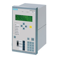
Siemens SIPROTEC 7UM62 Manual (94 pages)
Input/Output unit, Bay control unit, Communication module, PROFIBUS-DP Communication profile
Brand:
Siemens
| Category:
Protection Device
| Size: 0.65 MB
Table of Contents
Preface
3
Revision Index
7
Table of Contents
9
1 PROFIBUS Communication Modules
11
Communication Module Types and Hardware Revisions
12
Communication Module Types
12
Hardware Revisions
12
Compatibility of the Communication Module Hardware with PROFIBUS-DP Firmware Versions and Mapping Files
13
Display of Module-Specific Information at the SIPROTEC Device
15
Block 1: Status and Parameters of the PROFIBUS-DP Slave
17
Block 2: Firmware Versions and Mapping File
19
Block 3: Module Hardware Information and Boot Firmware Version
20
Block 4: OLM Information
21
Block 5: Status of the Event List Via PROFIBUS-DP
24
2 Parameters and Properties
25
Bus Specific Parameters
26
PROFIBUS-DP Settings
26
Configuration of the Fibre-Optical Interface
28
Event List Settings
31
PROFIBUS-DP Configuration Data
31
Execution of Switching Operations Via PROFIBUS-DP
32
Command Output Modes
32
Transformer Tap Change Commands
33
Behaviour under Special Operating Conditions
33
Response in the Event of Disturbed Communication to the PROFIBUS-DP Master
34
Communication Interruption
34
Signalling of Line-Breaks in a Redundant Fibre-Optical Ring
35
Annunciations to the PROFIBUS-DP Master
37
Event List Via PROFIBUS-DP (Sequence of Events Recorder)
38
Properties of the Event List
39
Structure of a PROFIBUS-DP Telegram with Event List
40
Telegram in Input Direction
40
Telegram in Output Direction
42
Handshake Mechanism
43
3 Data Type Definitions
45
Single-Point Indication (SP, Input)
46
Single Command (SC, Output)
47
Double-Point Indication (DP, Input) / Double Command (DC, Output)
48
Measured Value (Signed Integer)
49
Measured Value (Float)
50
Metered Measurand (Unsigned Long)
51
Transformer Tap Change Command (TC)
52
Transformer Tap Position Indication (TM)
53
Message Block for Event List Via PROFIBUS-DP
54
4 PROFIBUS-DP - Parameterization in DIGSI
57
Interface Selection and Mapping Files
58
Standard Mappings 3-1 to 3-N
58
Compatibility with Standard Mappings of Previous Versions
59
Interface Selection and Mapping Selection in DIGSI 4.21
59
Interface Selection and Mapping Selection in DIGSI 4.3 or Higher
63
Customization of the Allocations
66
Scaling of Measured Values
70
Measurement Conversion
70
Number Representation Depending on the Parameterization
71
Parameterization in DIGSI
73
Time Synchronization
75
PROFIBUS-DP Master
75
Parameterization in DIGSI
77
Using SFC14 and SFC15 in STEP7
79
5 Technical Data
83
Connection Via the PSE Module
84
Connection Via the PSO Module
86
Glossary
89
Index
91
Advertisement
Advertisement
Related Products
Siemens 7UM515
Siemens SIPROTEC 7UM61
Siemens SIPROTEC 7UT613 series
Siemens SIPROTEC 7UT63 series
Siemens SIPROTEC 7UT613*-*D/E series
Siemens SIPROTEC 7UT633*-* D/E series
Siemens SIPROTEC 7UT633*-* P/Q series
Siemens SIPROTEC 7UT635*-* D/E series
Siemens SIPROTEC 7UT635*-* P/Q series
Siemens SIPROTEC 7UT613*-* B series
Siemens Categories
Industrial Equipment
Controller
Control Unit
Oven
Washer
More Siemens Manuals
Login
Sign In
OR
Sign in with Facebook
Sign in with Google
Upload manual
Upload from disk
Upload from URL