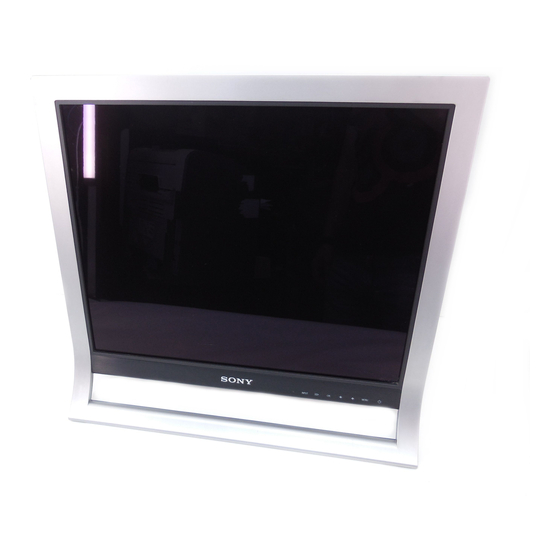
Sony SDM-HS95P Service Manual
Tft lcd color computer display
Hide thumbs
Also See for SDM-HS95P:
- Operating instructions manual (263 pages) ,
- Quick setup manual (21 pages) ,
- Safety manual (2 pages)
Summary of Contents for Sony SDM-HS95P
- Page 1 HISTORY Model Name : SDM-HS95P SERVICE MANUAL Part No. : 9-878-334-01 When clicking an item, it’s detail is displayed. Change of Date SUPP./CORR. Description of SUP/COR main text 2005.04 –...
- Page 2 SDM-HS95P US Model SERVICE MANUAL Canadian Model AEP Model Chinese Model TFT LCD COLOR COMPUTER DISPLAY...
- Page 3 There are some different LCD panels are used in the model SDM-HS95P . Therefore the repair parts are also different . Please confirm the serial number before repairing. Model name Colour Destination Serial Range Panel Plant SDM-HS95P SILVER 6,300,001-6,450,000 SDM-HS95P...
-
Page 4: Table Of Contents
: 418 mm 3-3. Operating Frequency Horizontal(Analog): 28 ~ 80kHz 8. WEIGHT (with TILT/SWIVEL) Horizontal(Digital) : 28 ~ 64kHz Vertical(Analog) : 48 ~ 75Hz Net. Weight : 6.0 kg Vertical(Digital) : 60Hz Gross Weight : 8.41 kg – 3 – SDM-HS95P (E) - Page 5 T. M. D. S. Data1/3 Shield T. M. D. S. Data3- T. M. D. S. Data3+ +5V Power Ground (return for +5V, H. Sync. and V. Sync.) T. M. D. S. (Transition Minimized Differential Signaling) – 4 – SDM-HS95P (E)
-
Page 6: Precautions
• If the surface of panel become dirty, please wipe it off with a softmaterial. (Cleaning with a dirty or rough cloth may damage the panel.) CAUTION Please use only a plastic screwdriver to protect yourself from shock hazard during service operation. – 5 – SDM-HS95P (E) -
Page 7: Servicing Precautions
ES heat sinks are correctly installed. device.) 8. Always connect the test receiver ground lead to the receiver chassis ground before connecting the test receiver positive lead. Always remove the test receiver ground lead last. – 6 – SDM-HS95P (E) - Page 8 2. Draw away the melted solder with an anti-static CAUTION: Maintain original spacing between the suction-type solder removal device (or with solder replaced component and adjacent components and the braid) before removing the IC. circuit board to prevent excessive component temperatures. – 7 – SDM-HS95P (E)
- Page 9 4. Route the jumper wire along the path of the out-away copper pattern and let it overlap the previously scraped end of the good copper pattern. Solder the overlapped area and clip off any excess jumper wire. – 8 – SDM-HS95P (E)
-
Page 10: Timing Chart
– 76.068Hz 31.216 1480 1170 1170x584 46.200 50Hz 50.026Hz 60.000 1800 1280 1280x960 108.000 60Hz 60.000Hz 1000 63.981 1688 1280 1280x1024 108.000 60Hz 60.020Hz 1066 1024 79.976 1688 1280 1280x1024 135.000 75Hz 75.025Hz 1066 1024 – 9 – SDM-HS95P (E) -
Page 11: Operating Instructions
This connector inputs digital RGB video signals that comply with DVI Rev.1.0. 10. HD15 (RGB) input connector (analog RGB) This connector inputs analog RGB video signals (0.7 Vp-p, positive) and SYNC signals. DDC (Display Data Channel) is a standard of VESA. – 10 – SDM-HS95P (E) -
Page 12: Disassembly
3) Please remove the screw cover at the Back cabinet, 6) Please pull the left side of Back cabinet like picture then screw cover will be departed. then latch will be departed. – 11 – SDM-HS95P (E) - Page 13 8) If Back cabinet will be departed easily, please pull 7) If Back cabinet will be departed easily, please pull upside edge of Back cabinet outside. bottom side of Back cabinet faced hinge outside. – 12 – SDM-HS95P (E)
-
Page 14: Exploded View
2. INITIAL EEPROM: Initialize the EDID DATA at DDC2B EEPROM is saved system memory. 3. CLEAR ETI: Initialize the used time of MFT. 4. AGING: Select aging mode. (on/off) 5. WHITE BALANCE: White balance adjustment 6. DEFAULT TIMING: Select default resolution timing. 7. MODULE: Select the module type. – 13 – SDM-HS95P (E) -
Page 16: Exploded View Parts List
POWER-SUPPLY CORD SET (CH), Black 1-827-757-11 D-SUB CABLE 1-827-758-11 DVI CABLE 4-102-356-21 CD-ROM 2-583-748-01 QUICK SETUP GUIDE (U/C) 2-583-748-11 QUICK SETUP GUIDE (AEP, CH) English Sony EMCS Corporation 2005DR02-1 Made in Japan Ichinomiya Tec 9-878-334-01 © 2005.4 – 15 – SDM-HS95P (E)


