Sign In
Upload
Manuals
Brands
Sony Manuals
Control Unit
HKCU-FP2
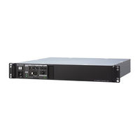
Sony HKCU-FP2 Manuals
Manuals and User Guides for Sony HKCU-FP2. We have
3
Sony HKCU-FP2 manuals available for free PDF download: Service Manual, Operation Manual
Sony HKCU-FP2 Service Manual (134 pages)
HD CAMERA CONTROL UNIT
Brand:
Sony
| Category:
Control Unit
| Size: 6.61 MB
Table of Contents
Table of Contents
5
Manual Structure
9
Purpose of this Manual
9
Related Manuals
9
Trademarks
9
Service Overview
11
Location of Printed Circuit Boards
11
Service Information
12
Note on Replacement of Lithium Battery
12
Flexible Card Wire
13
Connecting and Disconnecting Flexible Card Wires
13
Connecting and Disconnecting Flexible Card Wires with Connector
13
Updating the Software Programs
15
Updating the Main Program
15
Updating the BOOT Program
16
Writing and Rewriting the PLD Internal Data
17
Corresponding Plds
17
Periodic Replacement Parts
19
Notes on Replacement of Circuit Board
20
EEPROM Data
20
Actions to be Taken after Board Replacement/Repair
20
Circuit Protection Parts
21
Circuit Protective Element
21
Fuse
21
Functions of Onboard Parts
23
Description of Onboard LED Indicators
23
Functions of Onboard Switches
25
Functions of Onboard Potentiometers
26
Cleaning of Connector/Cable
27
When the Optical Connector Cleaner (Commercially Available) Is Available
27
When the Optical Connector Cleaner (Commercially Available) Is Not Available
28
Circuit Description
30
Board (Only in HSCU300R)
30
DPR-361 Board
31
Board (Only in HSCU300RF)
32
CN-3661 Board
33
CN-3662 Board
33
CN-3663 Board
33
AU-358 Board
33
CN-3664 Board
33
1-11-10. PS-739D Board
33
1-11-11. CT-257D Board
33
Lead-Free Solder
34
System Setup
35
System Connection
35
Audio System
36
Intercom System Setting
36
Microphone Setting
38
System Settings
40
Tally System
40
Camera Number Setting
40
Video Signal System
41
Input/Output Signal Selection
41
Signal Phase Adjustment
41
Aspect Ratio Setting for Down-Conversion
41
VBS Signal Level Adjustment
44
Waveform Monitor Signal Level Adjustment
44
Stair Case Signal Adjustment Procedure
45
Picture Monitor Signal Level Adjustment
45
RETURN Input Signal
46
Maintenance Mode
47
Preparations
47
Starting/Exiting the Maintenance Mode
47
Memory Stick
48
VE OPERATION Menu
49
MAINTENANCE Menu
59
MAINTENANCE Menu (HSCU300RF)
59
MAINTENANCE Menu (HSCU300R)
62
Replacement of Main Parts
67
General Information for Parts Replacement
67
Index
67
Tightening Torque
68
Top Cover
70
Front Assembly
71
Board (HSCU300R)
72
Board (HSCU300RF)
76
PS-739D Board
78
TRIAX Connector Assembly (HSCU300R)
80
Board (HSCU300R)
81
Board (HSCU300RF)
82
Board
83
CN-3664 Board
84
DC Fan (HSCU300R)
85
DC Fan (HSCU300RF)
87
Rear Assembly (HSCU300R)
89
Rear Assembly (HSCU300RF)
92
Board (HSCU300R)
94
Board (HSCU300RF)
96
Optical Multi Cable Assembly (HSCU300RF)
98
CN-3661 Board
100
CN-3662 Board
101
CN-3663 Board
102
Electrical Adjustment
103
Preparation
103
Equipment Required
103
Audio System Adjustment
105
RTS Intercom Adjustment Check
105
Video/Reference Signal System Adjustment
107
27 Mhz VCO Free-Running Adjustment
107
STAIR CASE Adjustment
108
SD Signal System Adjustment
109
VBS Output Level Adjustment
109
PIX Output Level Adjustment
109
WF Output Level Adjustment
110
Y/R-Y/B-Y Output Level Adjustment (SD)
111
HD Signal System Adjustment
113
Y/R-Y/B-Y Output Level Adjustment (HD)
113
RGB Output Level Adjustment
114
TRIAX Transmission System Adjustment
116
1.0-Mhz Modulation Circuit Adjustment
116
1.4-Mhz Demodulation Circuit Adjustment
116
Tone Detection Frequency Adjustment
117
Spare Parts
119
Note on Repair Parts
119
Exploded Views
120
Supplied Accessories
128
Diagrams
129
Block Diagrams
129
Frame Wiring
132
Advertisement
Sony HKCU-FP2 Service Manual (114 pages)
HD CAMERA CONTROL UNIT
Brand:
Sony
| Category:
Control Unit
| Size: 4.77 MB
Table of Contents
Table of Contents
5
Manual Structure
9
Purpose of this Manual
9
Related Manuals
9
Trademarks
9
1 Service Overview
11
Location of Printed Circuit Boards
11
Service Information
12
Note on Replacement of Lithium Battery
12
Flexible Card Wire
13
Connecting and Disconnecting Flexible Card Wires
13
Connecting and Disconnecting Flexible Card Wires with Connector
13
Updating the Software Programs
15
Updating the Main Program
15
Updating the BOOT Program
16
Writing and Rewriting the PLD Internal Data
17
Corresponding Plds
17
Periodic Replacement Parts
18
Notes on Replacement of Circuit Board
19
EEPROM Data
19
Actions to be Taken after Board Replacement/Repair
19
Circuit Protection Parts
20
Circuit Protective Element
20
Fuse
20
Functions of Onboard Parts
22
Description of Onboard LED Indicators
22
Functions of Onboard Switches
24
Functions of Onboard Potentiometers
25
Circuit Description
26
DM-152 Board
26
DPR-361 Board
27
CN-3661 Board
28
CN-3662 Board
28
CN-3663 Board
28
AU-358 Board
29
CN-3664 Board
29
PS-739D Board
29
1-10-10. CT-257D Board
29
Lead-Free Solder
30
2 System Setup
31
System Connection
31
Audio System
32
Intercom System Setting
32
Microphone Setting
34
System Settings
36
Tally System
36
Camera Number Setting
36
Video Signal System
37
Input/Output Signal Selection
37
Signal Phase Adjustment
37
Aspect Ratio Setting for Down-Conversion
37
VBS Signal Level Adjustment
40
Waveform Monitor Signal Level Adjustment
40
Stair Case Signal Adjustment Procedure
41
Picture Monitor Signal Level Adjustment
41
RETURN Input Signal
42
3 Maintenance Mode
43
Preparations
43
Starting/Exiting the Maintenance Mode
43
Memory Stick
44
VE OPERATION Menu
45
MAINTENANCE Menu
55
4 Replacement of Main Parts
59
General Information for Parts Replacement
59
Index
59
Tightening Torque
60
Top Cover
61
Front Assembly
62
Board
63
Board
67
PS-739D Board
67
TRIAX Connector Assembly
69
Board
70
CN-3664 Board
72
DC Fan
73
Rear Assembly
75
Board
78
CN-3661 Board
80
CN-3662 Board
81
CN-3663 Board
82
5 Electrical Adjustment
83
Preparation
83
Equipment Required
83
Audio System Adjustment
85
RTS Intercom Adjustment Check
85
Video/Reference Signal System Adjustment
87
27 Mhz VCO Free-Running Adjustment
87
STAIR CASE Adjustment
87
SD Signal System Adjustment
89
VBS Output Level Adjustment
89
PIX Output Level Adjustment
89
WF Output Level Adjustment
90
Y/R-Y/B-Y Output Level Adjustment (SD)
91
HD Signal System Adjustment
93
Y/R-Y/B-Y Output Level Adjustment (HD)
93
RGB Output Level Adjustment
94
TRIAX Transmission System Adjustment
96
1.0-Mhz Modulation Circuit Adjustment
96
1.4-Mhz Demodulation Circuit Adjustment
96
Tone Detection Frequency Adjustment
97
6 Spare Parts
99
Note on Repair Parts
99
Exploded Views
100
Supplied Accessories
107
7 Diagrams
109
Block Diagrams
109
Frame Wiring
112
Sony HKCU-FP2 Operation Manual (34 pages)
HD CAMERA CONTROL UNIT, CCU CONTROL PANEL
Brand:
Sony
| Category:
Control Unit
| Size: 1.04 MB
Table of Contents
Table of Contents
2
Overview
3
Features
3
System Configuration Example (HSCU300RF, Optical Digital Transmission)
5
System Configuration Example (HSCU300R, Digital Triax Transmission)
6
Locations and Functions of Parts
7
Front Panel
7
Rear Panel
8
HKCU-FP2 CCU Control Panel (Optional)
10
Status Display
12
Displaying the Status Screen
12
Status Display Screen
12
Setup Menu
16
Changing Menu Item Settings
16
Menu Tree
17
Menu List
19
Appendix
29
Notes on Use
29
Digital Triax Transmission (HSCU300R)
29
Error Messages
30
License Declarations
30
Specifications
30
Advertisement
Advertisement
Related Products
Sony HKCU-FP1
Sony HKCU-951
Sony HKCU-953
Sony HKCU-901CE
Sony HKCU-901J
Sony HKCU-902SY
Sony HKCU-904SY
Sony HKCU-701AM
Sony HKCU-702
Sony HKCU2040
Sony Categories
Laptop
TV
CD Player
Camcorder
Digital Camera
More Sony Manuals
Login
Sign In
OR
Sign in with Facebook
Sign in with Google
Upload manual
Upload from disk
Upload from URL