Sign In
Upload
Manuals
Brands
Honeywell Manuals
Measuring Instruments
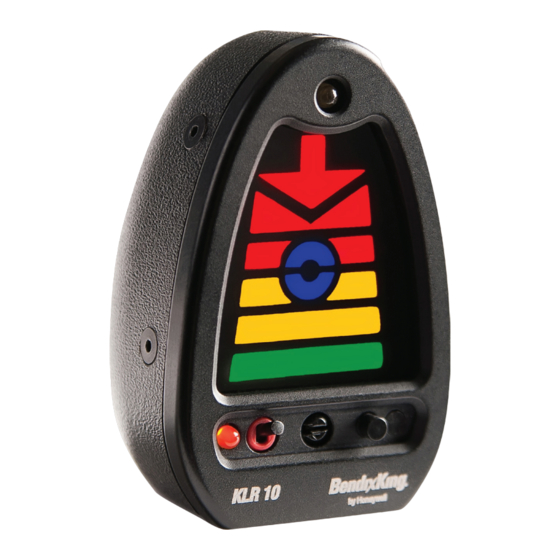
BendixKing KLR 10
User Manuals: Honeywell BendixKing KLR 10 Indicator
Manuals and User Guides for Honeywell BendixKing KLR 10 Indicator. We have
1
Honeywell BendixKing KLR 10 Indicator manual available for free PDF download: Installation Manual
Honeywell BendixKing KLR 10 Installation Manual (50 pages)
Lift Reserve Indicator
Brand:
Honeywell
| Category:
Measuring Instruments
| Size: 2.5 MB
Table of Contents
Table of Contents
7
General
11
Objective
11
References
11
Page and Subject Numbers
11
Revisions
11
Technical Support
11
Warranty Information
11
Standard Components
13
Optional Components
13
Table 1-2: KLR 10 Standard Kit Components
13
Table 1-3: KLR 10 Optional Components
13
KLR 10 Main Component Details
14
KLR 10 Indicator
14
Panel Mounting Kit
14
Figure 1-1: KLR 10 Indicator
14
Figure 1-2: Panel Mounting Kit
14
KLR 10 Swivel Mount Kit
15
KLR 10 Interface Module (if Module)
15
Figure 1-3: KLR 10 Swivel Mount
15
Figure 1-4: KLR 10 Interface
15
KLR 10 AOA Probe
16
Figure 1-5: AOA Probe Sensor Fittings
16
Figure 1-6: Mounting Plate
16
Planning
17
Preparation
17
Establish the Location for the KLR 10 Indicator
17
Establish the Location for the if Module
18
Establish the Location for the AOA Probe
19
Figure 2-1: AOA Probe in Wing
19
Establish a Plan to Route the Sense Lines
20
Establish a Plan for the Electrical Power
20
Optional Probe Heat Installation
20
Review Your Plans
21
Installation
23
Installation of the Probe Mounting Plate
23
Installation of the Sense Lines
23
Figure 3-1: Mounting Plate Alignment
23
Install Wiring, Switch & Circuit Breaker for KLR 10
24
Install Wiring, Switch & Circuit Breaker for Probe Heat
24
Install the KLR 10 Swivel Mount (Optional)
26
Glareshield Mounting Instructions
26
Figure 3-2: Swivel Mount on Glareshield
26
Figure 3-3: Swivel Mount Template
26
Installation of the KLR 10 Indicator
28
Installation of the if Module
28
Figure 3-7: KLR 10 Interface Module Electrical Connectors
29
Figure 3-8: KLR 10 Interface Module Sense Line Connectors
29
Installation of AOA Probe
30
Figure 3-9: AOA Probe Pin Positions- Left Side
30
Figure 3-10: AOA Probe Pin Positions- Right Side
30
Figure 3-11: Correct Position of Probe Lock Plate
31
Figure 3-12: Enlarging Mounting Plate Hole
31
Inspect the KLR 10 Installation
32
Figure 3-13: AOA Probe Connectors
32
Setup and Calibration
33
On the Ground Zero Pressure Calibration
33
Failure to Complete Zero Pressure Ground Calibration
33
SET Brightness of the KLR 10 Indicator (Optional)
34
Master Volume Set
35
In-Flight Calibration Overview
35
Figure 4-1: Master Volume Controls
35
In-Flight Optimum Alpha Angle (OAA) Calibration
37
In-Flight Cruise Set Point Calibration
38
Exiting the Calibration Mode
39
Completing the Calibration
40
Table 4-1: Indications and Annunciations During Calibration
41
Figure 4-2: OAA Setpoint Flowchart
42
Figure 4-3: Cruise Setpoint Flowchart
43
Appendix
45
Acronyms and Abbreviations
45
IF Module Connectors Pin Definitions
46
Table 5-1: Power Connector
46
Table 5-2: Auxiliary I/O Connector
46
Table 5-3: Display Connector
46
AOA Probe Angles
47
Positive Probe Lock System
47
Figure 5-1: Right Side Angles
47
Figure 5-2: Left Side Angles
47
Limitations
48
Honeywell-Confidential
49
Copyright - Notice
50
Advertisement
Advertisement
Related Products
Honeywell KA 54
Honeywell Bendix/King KRA 405B
Honeywell Bendix/King KN 63
Honeywell BendixKing KN 62A
Honeywell BendixKing KN 62
Honeywell BendixKing KN 64
Honeywell BENDIXKING KNI 416
Honeywell BENDIX/KING KRA 405
Honeywell BENDIX/KING KLN 94
Honeywell KLN 90B GPS
Honeywell Categories
Thermostat
Controller
Control Unit
Security Camera
Accessories
More Honeywell Manuals
Login
Sign In
OR
Sign in with Facebook
Sign in with Google
Upload manual
Upload from disk
Upload from URL