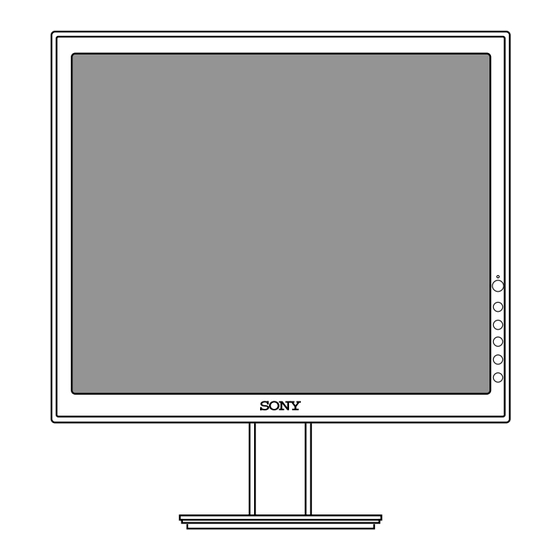
Sony SDM-S53 Service Manual
Tft lcd color computer display
Hide thumbs
Also See for SDM-S53:
- Guide utilisateur (22 pages) ,
- Safety manual (2 pages) ,
- Specifications (2 pages)
Table of Contents
Advertisement
Quick Links
Download this manual
See also:
Manual
Advertisement
Table of Contents

Summary of Contents for Sony SDM-S53
- Page 1 SDM-S53 US Model SERVICE MANUAL Canadian Model AEP Model Chinese Model TFT LCD COLOR COMPUTER DISPLAY...
- Page 2 There are some different LCD panels are used in the model SDM-S53. Therefore the repair parts are also different. Please confirm the serial number before repairing. MODEL NAME COLOR Dest. SER.NO (LPL) SER.NO (CMO) SDM-S53 (Korea) GRAY 9,000,001-9,120,000 9,120,001-9,200,000 SDM-S53 (Korea)
-
Page 3: Table Of Contents
: 0.467 Vp-p c) Color 15, 0 : 0.714 Vp-p 3) Input Impedance : 75 3-3. Operating Frequency Horizontal : 28 ~ 61kHz Vertical : 48 ~ 75Hz Max. Resolution Analog : 1024 x 768 / 75Hz – 3 – SDM-S53 (E) -
Page 4: Precaution
• If the surface of panel become dirty, please wipe it off with a softmaterial. (Cleaning with a dirty or rough cloth may damage the panel.) CAUTION Please use only a plastic screwdriver to protect yourself from shock hazard during service operation. – 4 – SDM-S53 (E) -
Page 5: Timing Chart
– 53.946 1328 1024 1024x768 71.640 66Hz – 66.110Hz – 56.476 1328 1024 1024x768 75.000 70Hz – 70.069Hz 60.023 1312 1024 1024x768 78.750 75Hz 75.029Hz 1024x768 – 60.241 1328 1024 (MAC19”) 80.000 – 74.927Hz 75Hz – 5 – SDM-S53 (E) -
Page 6: Operating Instructions
This button actives tge selected menu item and adjustments made using the buttons( 5. ECO Button This button is used to reduce the power consumption. REAR VIEW HD15(RGB) input connector Main Power Switch AC IN connector – 6 – SDM-S53 (E) -
Page 7: Wiring Diagram
WIRING DIAGRAM Connector Ass’y P/N: 1-900-280-95 J704 J707 J706 AC switch with connector P/N 1-786-624-11 – 7 – SDM-S53 (E) -
Page 8: Block Diagram
BLOCK DIAGRAM – 8 – SDM-S53 (E) -
Page 9: Lips Board Block Diagram
LIPS Board Block Diagram 50 ~ 60Hz 100KHz HVDC INPUT RECTIFIER ENERGY OUTPUT RECTIFIER COMPONENTS AND FILTER TRANSFER AND FILTER LINE 100 ~ 240V SIGNAL PHOTO- COLLECTI CONTROL COUPLER CIRCUIT ISOLATION PRIMARY SECONDARY – 9 – SDM-S53 (E) -
Page 10: Adjustment
Select “9300K” in “COLOR TEMP” and enter. 1) Prepare timing and pattern data for a signal b. Use a 35%(89Gray) IRE white video field in the generator according to the Sony timing primary mode. specifications. c. Adjust “SUB CONTRAST “ to secure the color 2) Connect a monitor video cable to the signal temperature. -
Page 12: Exploded View Parts List
4-097-036-01 INDIVIDUAL CARTON (Gray), Korea 3890TSE449A 4-100-639-01 INDIVIDUAL CARTON (Gray), China 4-097-037-01 INDIVIDUAL CARTON (Black), Korea 3890TSE449B 4-100-640-01 INDIVIDUAL CARTON (Black), China English 2004CR02-1 Sony EMCS Corporation Made in Japan 9-878-218-01 © 2004. 3 Ichinomiya Tec SDM-S53(E) – 12 –...

