Advertisement
Quick Links
12
GFK-0164G
August 1997
Coprocessor Modules
Programmable Coprocessor Module (
datasheet GFK-0164G
Features
Single slot Coprocessor
Dual Tasking
t
MegaBasic
CCM2 Protocol
12 Mhz, 80C186 microprocessor
r
90% of an IBM
AT performance
Up to 96 Kbytes battery-backed CMOS logic and
data memory on board
Supports up to 512 Kbytes optional expansion
memory
Programmed by IC647, IC640 or IBM-compatible
Personal Computer
Two RS-422/RS-485 or RS-232 serial ports
High performance access to PLC memory
Real time calendar clock synchronized to PLC
Reset pushbutton
Three Status LEDs
Soft Configuration (No dip switches or jumpers)
r
with MS-DOS
or Windows
software configuration function
Simultaneous communications on both ports at up
to 9.6 Kbaud, or up to 19.2 Kbaud individually.
Functions
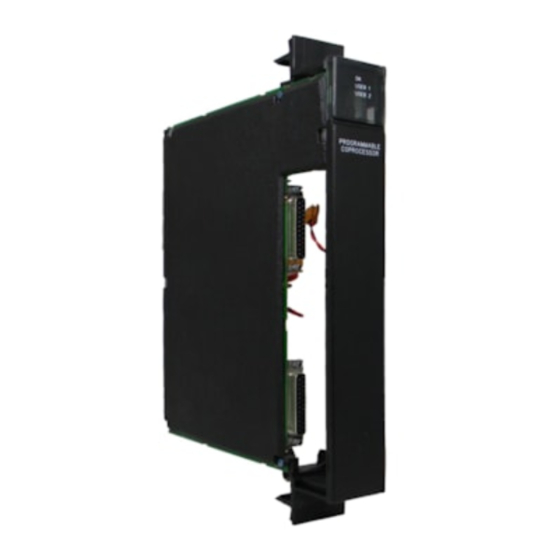
The Programmable Coprocessor Module (PCM) is a
Coprocessor to the PLC CPU. It can be programmed
to perform operator interface, real time computations,
data storage, data acquisition and data communica-
tions functions. It communicates with the PLC CPU
over the backplane and can access user and system
data using extensions to the powerful MegaBasic lan-
guage. No application program support is required in
the PLC CPU.
Many PCMs can be supported in a single IC697 PLC
system and each can accommodate an optional ex-
pansion memory up to 512 Kbytes.
t
MegaBasic is a trademark of Christopher Cochran;
r
MS-DOS and Windows are registered trademarks of Microsoft Corporation.
1
)
IC697PCM711
r
based programming
r
IBM is a registered trademark of International Business Machines Corporation.
Coprocessor Modules
Programmable Coprocessor Module
Î Î
OK
Î Î
USER 1
USER 2
Î Î
PCM 711
COPROCESSOR
Î
Dual tasking allows running a MegaBasic program at
the same time the PCM is used as a communications
interface. Operation of the module may be initialized
by a pushbutton or by an attached PCM development
system. The status of the PCM is indicated by three
green LEDs on the front of the module.
IC697PCM711
a44716
Î Î
Î
Î Î
Î
Î Î
Î Î
Î
Î Î
Î
Î Î
Î Î
Î
Î
Î Î
Î Î
Î Î
Î Î Î Î
Î Î
Î
Î Î
PCM 711
Î Î
Î Î Î Î
Î
MODULE OK
Î
Î
USER 1
USER 2
Î Î Î Î
Î Î
Î Î
Î
Î
ON = OK, ACTIVE
OR USER
PUSH TO RESTART
Î Î
Î
APPLICATION
PUSH AND HOLD TO
STOP AND RESET
Î
Î Î
BATTERY
Î
Î Î
CONNECTIONS
Î Î
Î Î Î Î
INSTALL NEW
BATTERY BEFORE
UNPLUGGING OLD
BATTERY. USE
IC697ACC701
Î
Î Î
PORT 1
Î
Î Î
RS–232 OR
RS–422/485
Î Î Î Î
Î Î
COMPATIBLE
MODULE FUNCTION
PROGRAMMABLE
Î Î
Î
COPROCESSOR,
COMMUNICA TIONS
Î Î
Î
OPTIONAL MEMORY
USE IC697MEM71
Î
Î Î
PORT 2
Î Î Î Î
Î Î
RS–232 OR
RS–422/485
COMPATIBLE
MODULE
Î Î
Î
IC697PCM711
LABEL
Î Î
Î
44A726758–203
Advertisement

Summary of Contents for IBM MegaBasic IC697PCM711
- Page 1 The status of the PCM is indicated by three green LEDs on the front of the module. MegaBasic is a trademark of Christopher Cochran; IBM is a registered trademark of International Business Machines Corporation. MS-DOS and Windows are registered trademarks of Microsoft Corporation.
- Page 2 Coprocessor Modules GFK-0164G Programmable Coprocessor Module August 1997 Installation Expansion Memory The PCM can operate with or without an expansion Installation should not be attempted without refer- ring to the applicable Programmable Controller memory daughter board. The base memory on the Installation Manual (see reference 5).
- Page 3 Programmable Coprocessor Module GFK-0164G August 1997 Programming and Configuration Table 1. Port 1 or 2 - RS-232 An IC647 or IC640 computer, or IBM-compatible PC, SIGNAL NAME FUNCTION XT, or AT computer with PCM Development Software installed is connected to the top port of the PCM. The Shield default setting is 19,200 bps.
- Page 4 Coprocessor Modules GFK-0164G Programmable Coprocessor Module August 1997 If during power-up diagnostics a low battery is detected Batteries the Module OK LED (top) will not stay on. Specific in- A lithium battery (IC697ACC701) is installed as shown dication of a low battery state is detailed in the PCM in figure 2.


