Sign In
Upload
Manuals
Brands
Sony Manuals
Digital Camera
HDC1550
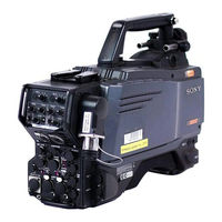
Sony HDC1550 Manuals
Manuals and User Guides for Sony HDC1550. We have
3
Sony HDC1550 manuals available for free PDF download: Maintenance Manual, Operation Manual
Sony HDC1550 Maintenance Manual (550 pages)
HD COLOR CAMERA
Brand:
Sony
| Category:
CCD Cameras
| Size: 66.13 MB
Table of Contents
Table of Contents
3
Manual Structure
8
Purpose of this Manual
8
Related Manuals
8
Spare Parts
9
Notes on Repair Parts
9
Exploded Views
11
Hdc1000/1100
11
Hdc1400/1450/1500/1550/1580/1600
24
Electrical Parts List
43
Optional Fixtures
245
Supplied Accessories
245
Hdc1000/1100
245
Hdc1400/1450/1500/1550/1580/1600
245
Overall (HDC1000/1100/1400/1450/1500/1550/1600)
252
Overall (HDC1580)
253
Dpr-265C
259
Sdi-84C
261
Cn-2621Ga
267
4-33
267
4-37
267
Dpr-265C
267
Mb-1059/1059G/1059Ga
267
4-95
267
Sdi-84C
381
Frame Wiring HDC1000/1100
452
Frame Wiring (HDC1500/1550/1600/1400/1450)
453
Frame Wiring HDC1580
454
Board Layouts
455
5-15
455
5-16
455
Mb-1059G
499
Advertisement
Sony HDC1550 Maintenance Manual (144 pages)
HD COLOR CAMERA Digital HDVS
Brand:
Sony
| Category:
Digital Camera
| Size: 6.09 MB
Table of Contents
Table of Contents
5
Manual Structure
8
Purpose of this Manual
8
Related Manuals
8
1 Service Overview
9
Checking before Installation
9
Checking the ROM and Software Version
9
Connectors and Cables
10
Connector Input/Output Signals
10
Wiring Diagrams for Cables
17
Connection Connectors/Cables
18
Note in Connecting CCU Connector
18
(Hdc1000/1400/1500/1580)
18
Location of Printed Circuit Boards
19
Opening/Closing the Side Panel
22
Switch Settings
23
Notes for Replacing Parts
27
Notes for Replacing the Flexible Card Wire
27
Notes for Replacing the Board
28
Notes for Replacing the Connector on the Board
28
Notes for HDC1400 and HDC1580
28
Cleaning the Vent Portion of the Fan (HDC1400/1500/1550/1580)
29
Cleaning of Connector/Cable (HDC1000/1400/1500/1580)
30
When the Optical Connector Cleaner
30
(Commercially Available) Is Available
30
When the Optical Connector Cleaner
31
Setting the Utility out Voltage (HDC1000)
32
Notes on Flexible Card Wire
32
Disconnecting/Connecting Flexible Card Wire
32
Forming of the Flexible Card Wire
34
Notes on Replacement of Circuit Board
35
Description on EEPROM Data
35
Adjustment after Replacement of Board
35
Adjustment and Setting Items When
35
Replacing AT-163 Board
35
Setting Microphone Power and Intercoms
36
Setting Intercoms
36
Upgrading the Software
37
Upgrading the MAIN Program
37
Upgrading the Boot Program
38
Writing and Rewriting the PLD Internal Data
39
Note on Replacement of Lithium Battery
40
Recommended Replacing Parts
41
Hdc1000
41
Hdc1400/1500/1550/1580
42
Periodic Check/Replacement Parts
43
Description of CCD Block Number
44
Optional Fixtures
44
Notes on Repair Parts
44
Unleaded Solder
44
2 Replacement of Main Parts
45
Replacing the CCD Unit
45
Hdc1000
45
Hdc1400/1500/1550/1580
47
Replacement of CCD Unit Boards
48
Board
48
CN-2579 Board
48
Board
49
CN-2578 Board
50
Replacing the Filter Disk Unit
51
Hdc1000
51
Hdc1400/1500/1550/1580
51
Replacing the Fan (HDC1000)
52
DC Fan (TOP)
52
Replacing the Fan (HDC1400/1500/1550/1580)
53
DC Fan (Front)
53
DC Fan (Rear)
54
Replacing the VF DISP Switches (HDC1400/1500/1550/1580) (SW-1237 Board)
55
Replacing the Side Switch Panel Assembly (HDC1400/1500/1550/1580) (SW-1240 Board)
56
Replacing the Connectors (HDC1400/1500/1550/1580)
56
EARPHONE Jack (CN-2640 Board)
56
DC in Connector (CN-2623 Board)
57
INTERCOM 1/2 Connector
58
(CN-2618 Board)
58
LENS Connector (CN-2616 Board)
58
MIC 1 in Connector (CN-2615 Board)
59
REMOTE Connector (CN-2622 Board)
59
RET IN, TEST out Connector
60
(CN-2620 Board)
60
SDI 1 Connector (HDC1500)
60
SDI 2 Connector (HDC1500)
61
SDI Connector (HDC1400/1550)
61
BUILD up Connector
61
(Hot Shoe Assembly)
61
Replacing the Encapsulated Cable Assembly/Triax Assembly
62
HDC1000 (Encapsulated Cable Assembly)
62
HDC1400/1500/1580 (Encapsulated Cable Assembly)
63
HDC1550 (TRIAX Assembly)
64
Replacing the DC/DC Converter Unit
65
Hdc1000
65
Hdc1400/1500/1550/1580
65
Replacing the Switching Regulator
66
Hdc1000
66
Hdc1400/1500/1580
67
Hdc1550
68
Replacing the Boards (HDC1000)
69
MB-1060 Board
69
Replacing the Boards (HDC1400/1500/1550/1580)
72
CN-2617 Board
72
MB-1059 Board
73
Checking SDI-84 Board (HDC1400/1500/1580)
74
3 Electrical Alignment
75
Preparations
75
Equipment Required
75
Precautions on Adjustments
75
File Data at Adjustment
75
Maintaining the Grayscale Chart
76
Description on Setup Menu
78
Connection of Equipment
79
Initial Settings
80
Adjustment Items and Setup Menu Items
81
Automatic Adjustment
82
Electrical Alignment
82
Clamp Level Adjustment between Channel a and Channel B
82
BLACK SET Adjustment
83
Sensitivity Adjustment
83
V-SUB Adjustment
84
BLACK SHADING Adjustment
85
White Shading Adjustment
85
RPN Adjustment
87
Video System Level Adjustment
88
H/V Ratio Adjustment
88
Detail Level Adjustment
89
Crispening Adjustment
89
Level Dependent Adjustment
90
Detail Clip Adjustment
90
Auto-Iris Adjustment
91
Pedestal Level Adjustment
92
Flare Adjustment
92
Gamma Correction Adjustment
93
Knee Point/Knee Slope Adjustment
93
White Clip Level Adjustment
94
File Store
95
ND Offset Adjustment
96
Adjustment Preparation of HDC1550
97
Equipment Required
97
Precautions on Adjustments
97
Connection
98
TONE Adjustment (HDC1550)
99
CCU DATA Demodulation Adjustment
99
Video System Adjustment (HDC1550)
100
Demodulation Tuning Adjustment
100
Return Sync Level Adjustment
100
Return Frequency Adjustment
101
74 Mhz Clock Duty Adjustment
102
CHU y Level Adjustment
102
CHU C Level Adjustment
102
Prompter Adjustment
103
Return DC Level Adjustment
105
Audio System Adjustment (HDC1550)
106
Frequency Adjustment
106
Audio Modulation Adjustment
107
INCOM 1 Demodulation/Output Level Adjustments
108
INCOM 2 Demodulation/Output Level Adjustments
109
PGM 1 Demodulation/Output Level Adjustments
110
PGM 2 Demodulation/Output Level Adjustments
111
RPN Compensation
112
Automatic Compensation (APR)
112
Manual RPN Compensation Adjustment
112
Procedures to be Taken When the RPN
113
Performing Automatic RPN Detection
114
Effectively
114
RPN Compensation Flowchart
115
4 File System
117
File Structure
117
Operator File
118
Preset Operator File
119
Scene File
120
Reference File
122
Lens File
124
OHB File
126
File Items
128
5 Setup Menu
137
Entering the SERVICE Menu
137
Settable Special Functions
138
Black Shading
139
Sony HDC1550 Operation Manual (65 pages)
HD Color Camera
Brand:
Sony
| Category:
Camcorder
| Size: 4 MB
Table of Contents
Table of Contents
4
Overview
5
Features
5
System Configuration
7
Connection Example
10
Precautions
11
Phenomena Specific to CCD Image Sensors
11
Locations and Functions of Parts
12
Accessory Attachments
12
Controls and Connectors
13
Preparations
21
Attaching a Lens
21
Adjusting the Flange Focal Length
21
Attaching a Viewfinder
21
Adjusting the Shoulder Pad Position
23
Mounting the Camera to a Tripod
24
Adjustments and Settings for Recording
25
Adjusting the Black Balance and White Balance
25
Adjusting the White Balance
26
Setting the Electronic Shutter
28
Setting the Camera Outputs
29
Viewfinder Screen Status Display
32
Menu Operations
33
Starting Menu Operations
33
Selecting Pages
34
Setting the Menu Items
35
Editing the USER Menu
35
Menu List
39
OPERATION Menu
39
PAINT Menu
44
MAINTENANCE Menu
48
FILE Menu
51
DIAGNOSIS Menu
53
Using a "Memory Stick
54
Using a “Memory Stick”
56
Specifications
56
Hdc1500
56
Hdc1550
57
Hdc1400
59
Hdc1450
60
Advertisement
Advertisement
Related Products
Sony HDC1400
Sony HDC1000 series
Sony HDC1580
Sony HDC4800
Sony HDCU-F950
Sony HDC-P50
Sony HDC-P31
Sony HDR-280E
Sony HDR-320E
Sony HDR-390E
Sony Categories
Laptop
TV
CD Player
Camcorder
Digital Camera
More Sony Manuals
Login
Sign In
OR
Sign in with Facebook
Sign in with Google
Upload manual
Upload from disk
Upload from URL