Sign In
Upload
Manuals
Brands
Sony Manuals
VCR
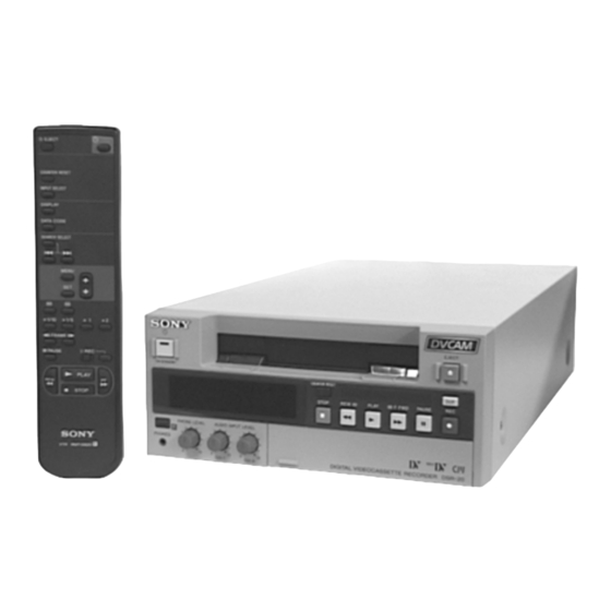
DSR-20MD
Sony DSR-20MD Manuals
Manuals and User Guides for Sony DSR-20MD. We have
2
Sony DSR-20MD manuals available for free PDF download: Service Manual, Instructions For Use Manual
Sony DSR-20MD Service Manual (225 pages)
DIGITAL VIDEO CASSETTE RECORDER
Brand:
Sony
| Category:
VCR
| Size: 35.93 MB
Table of Contents
Service Note
4
Table of Contents
5
General
8
Disassembly
18
Removal of Upper Case
18
Removal of Front Panel Assembly
18
Removal of VA-102 Board
18
Removal of Power Block
18
Removal of MD Block Assembly
19
Removal of CM-56 Board
19
Removal of JC-19 Board
19
Removal of RP-228 Board
19
Circuit Boards Location
20
Overall Block Diagram 1
21
Overall Block Diagram 2
22
Overall Block Diagram 3
23
Overall Block Diagram 4
24
Overall Block Diagram 5
25
Overall Block Diagram 6
26
Printed Wiring Boards and Schematic Diagrams
27
Frame Schematic Diagrams
28
Frame (1/2) Schematic Diagram
28
Frame (2/2) Schematic Diagram
29
Printed Wiring Boards and Schematic Diagrams
30
Printed Wiring Board
30
Printed Wiring Board
34
AD/DA CONVERTER) Schematic Diagram
36
S1 AFC) Schematic Diagram
38
U1) Schematic Diagram
40
D1) Schematic Diagram
43
C1 SPCON) Schematic Diagram
44
MODE) Schematic Diagram
47
DV IN/OUT) Schematic Diagram
48
AUDIO CORE) Schematic Diagram
50
DIGITAL AUDIO) Schematic Diagram
51
AUDIO D/A, A/D CONVERTER) Schematic Diagram
53
Printed Wiring Board
54
Printed Wiring Board
56
IF) Schematic Diagram
58
VIDEO IN) Schematic Diagram
59
VIDEO OUT) Schematic Diagram
60
UVIC & DV IN/OUT) Schematic Diagram
63
MONITOR OUT) Schematic Diagram
64
AUDIO) Schematic Diagram
65
HI MICOM) Schematic Diagram
67
Printed Wiring Board
69
RS MICOM) Schematic Diagram
70
Printed Wiring Boards
71
Printed Wiring Board
73
Printed Wiring Board
75
Printed Wiring Board
79
Printed Wiring Board
82
Waveforms
86
Printed Parts Location
91
Adjustments
93
Mechanical Section Adjustments
93
Information
93
How to Search Reference Pages for Removal
93
Phase Adjustment Mark " PH
93
Preparation for Mechanical Check, Adjustment and Maintenance
94
FL Block Assembly
94
Cassette Positions
94
Loading/Unloading
95
Manual Up/Down the FL Block
95
Service Jigs List
96
Phase Adjustments
98
Phase Adjustment (Loading/Unloading Driving Section)
98
Phase Adjustment (S/L Cassette Selection Section)
100
Phase Adjustment (Mechanism Chassis Upper Surface Parts)
102
Periodic Check and Maintenance
104
Cleaning of Rotary Drum Assembly
104
Cleaning of Tape Path System
104
Periodic Checks
105
Mechanism Section Checks and Replacements
106
Tape Stopper, Motor FPC Assembly and Elastic Connector
106
Drum Assembly and Drum Base
106
LM Cover, LM Worm Wheel, LM Holder and LM Motor Assembly
107
TG3/4 Catcher Block Assembly, Pinch Driving Gear and TC Arm Assembly
107
Pinch Arm Assembly, Pinch Limiter and Tension Coil Spring (Pinch)
108
HC Arm, HC Roller Assembly
108
TG5/6 Catcher Block Assembly
108
RL Arm and RL Link
109
Gooseneck Guard and Gooseneck Arm Assembly
109
Tension Coil Spring (TG2), Spring Adjustor
110
Tension Coil Spring (TG7), Spring Adjustor and TG7 Spring Hook
110
TG2 Retainer, TG2 Arm Assembly (TG2 Plate Spring and ET Magnet), S Tension Regulator Band Assembly and TG2 Load Arm Assembly
111
TG7 Retainer, TG7 Arm Assembly (TG7 Plate Spring and ET Magnet), T Tension Regulator Band Assembly and TG7 Load Arm Assembly
112
S Reel Table Block Assembly
113
T Reel Holder and T Reel Table Block Assembly
114
S Reel Plate Assembly
114
T Reel Plate Assembly
116
TG1/8 Base Assembly, S Brake and T Ratchet
117
TG3/6 Roller Assembly and TG3/6 Lock Spring
118
FL Joint Gear, TG5/6 Retainer and Capstan Motor
118
FL Selection Arm, FL Relay Gear and FL Joint Arm Assembly
119
Rotary Switch, TC Gear and Relay Gear
119
GL Arm Retainer and GL Arm
120
M Slider and M Slider Arm
120
Tg7 Selection Arm, Tg7 Cam Gear Andt Cam Gear
120
Main Cam, TG2 SL Arm Assembly and Tension Coil Spring (TG2 SL)
121
TG3/4 Arm Block Assembly (TG3/4 Arm Assembly, TG3/4 Limiter Spring and TG3/4 Gear), TG3/4 Base Block Assembly (TG3/4 Base Assembly)
122
TG5/6 Arm Block Assembly (TG5/6 Arm Assembly, TG5/6 Limiter Spring and TG5/6 Gear), TG5/6 Base Block Assembly (TG5/6 Base Assembly)
124
Reel Motor
126
RS Arm Assembly
126
RS Gear Assembly, MIC Press Spring and MIC Lever
126
Rack Joint Gear, Rack Holder, MIC Holder, Rack (LC) and Rack (SC)
127
Plate Link Assembly
128
Roller Shaft Assembly and Roller Belt
130
Lid Opener
131
C Door
132
Damper Arm and Tension Spring (DB)
132
Gear (A), Gear (B) and C Worm
132
Spring and C Sloat Block Assembly
133
Adjustments and Checks
134
Adjustment Position
134
Adjustment Order
135
Adjustment and Checking Method
136
Reel Table Height Adjustment
136
TG2/TG7 Height Adjustment
137
FWD/RVS Position Adjustment
137
TG2/TG7 Electric Tension Regulator Adjustment
138
FWD/RVS Back Tension Adjustment
140
Adjustment Preparations and RF Waveform Check
141
Tracking Adjustment
142
Tracking Check
143
CUE and REV Check
144
Rising Check
145
Tape Path Check
146
Service Mode
147
Adjusting Remote Commander
147
Used Adjustment Remote Commander
147
Precautions Upon Using the Adjusting Remote Commander
147
Data Processing
148
Service Mode
149
Emergence Memory Address
149
EMG Code (Emergency Code)
149
Video Section Adjustments
150
Preparations before Adjustment
150
Equipment Used
150
Connection of Equipment
150
Adjusting Connectors (RP 228 Board CN775)
151
Checking the Input Signals
152
S Video Input
152
Video Input
152
Input/Output Level and Impedance
154
Power Supply System Adjustment
154
Power Supply Voltage Check, Power Block (U-2 Board)
154
Video/Audio Block Power Supply Voltage Check Power Block (U-2 Board)
154
System Control System Adjustment
155
Initializing the C, D, E
155
Input of C Page Initial Data
155
Input of D Page Initial Data
155
Input of E Page Initial Data
155
Modification of C, D, E
155
Page C Address List
156
Page D Address List
156
Page E Address List
157
Servo System Adjustments
158
Switching Position Adjustment (CM-56 Board)
158
Capstan FG Duty Adjustment (CM-56 Board)
158
Video System Adjustments
159
Board Adjustments
159
Recording Current Adjustment (RP-228 Board)
159
PLL Fo Adjustment (RP-228 Board)
159
CLK Delay Adjustment (RP-228 Board)
160
AGC Center Level Adjustment (RP-228 Board)
160
AEQ Adjustment (RP-228 Board)
161
PLL Capture Range Adjustment (RP-228 Board)
162
IC774 41.85 Mhz VCO Check (RP-228 Board)
162
Board Adjustments
163
A/D Converter Reference Voltage Adjustment
163
(JC-19 Board)
163
Y Signal Clamp Reference Voltage Adjustment (JC-19 Board)
163
CR Signal Clamp Reference Voltage Adjustment (JC-19 Board)
163
CB Signal Clamp Reference Voltage Adjustment (JC-19 Board)
163
Playback y Signal Level Adjustment (JC-19 Board)
164
Playback CR Signal Level Adjustment (JC-19 Board)
164
Playback CB Signal Level Adjustment (JC-19 Board)
165
IC422 27Mhz XTAL Fo Adjustment (JC-19 Board)
165
AFC Preliminary Adjustment (JC-19 Board)
165
AFC Picture Frame Adjustment (JC-19 Board)
166
AFC Adjustment (JC-19 Board)
166
Board Adjustments
167
AGC Adjustment (VA-102 Board)
167
Analog E-E VIDEO Signal Output Level Adjustment (VA-102 Board)
167
Analog E-E y Signal Output Level Check (VA-102 Board)
168
Analog E-E Chroma Signal Output Level Check (VA-102 Board)
168
Decoder VXO Freerunning Frequency Adjustment (VA-102 Board)
169
Video Input Y/C Separation Adjustment (VA-102 Board)
169
Decoder HUE Adjustment (VA-102 Board)
170
REC y Level Adjustment (VA-102 Board)
171
REC CR Level Adjustment (VA-102 Board)
171
REC CB Level Adjustment (VA-102 Board)
172
Encoder Freerunning Frequency Adjustment (VA-102 Board)
172
Playback y Level Check (VA-102 Board)
172
Playback Chroma Level Adjustment (VA-102 Board)
173
Playback Burst Level Adjustment (VA-102 Board) (PAL Model Only)
173
General Adjustment
174
Y Output Level Adjustment (JC-19 Board)
174
Encoder R-Y Input Level Adjustment (JC-19 Board)
174
Encoder B-Y Input Level Adjustment (JC-19 Board)
175
Decoder HUE Input Adjustment (JC-19 Board)
175
Battery down Adjustment and Confirmation
176
BIST Check
177
Playback System Check (JC-19, RP-228 Boards)
177
Record System Check
178
Audio System Adjustments
179
Playback Level/Indicator Check
179
E-E Level Check
179
Recording/Playback Check (Audio Lock Mode)
179
Arrangement Diagram for Adjustment Parts
179
Repair Parts List
181
Exploded Views
181
Overall Assembly
181
Chassis Assembly
182
MD Block Assembly
183
Mechanism Chassis Assembly
185
(Top Side View (1))
185
Mechanism Chassis Assembly
186
(Top Side View (2))
186
Mechanism Chassis Assembly
187
(Top Side View (3))
187
(Bottom Side View (1))
188
Mechanism Chassis Assembly
188
(Bottom Side View (2))
189
Electrical Parts List
190
Hardware List
222
Advertisement
Sony DSR-20MD Instructions For Use Manual (49 pages)
Digital Video cassette Recorder
Brand:
Sony
| Category:
VCR
| Size: 3.87 MB
Advertisement
Related Products
Sony DSR-20/20P
Sony DSR-2000P
Sony DSR-2000
Sony DVCAM DSR-25
Sony DSR-20
Sony DSR-20P
Sony DSR-20MDP
Sony DSR 25 - DVCAM Digital Video Recorder
Sony DSR-70
Sony DVCAM DSR-50P
Sony Categories
Laptop
TV
CD Player
Camcorder
Digital Camera
More Sony Manuals
Login
Sign In
OR
Sign in with Facebook
Sign in with Google
Upload manual
Upload from disk
Upload from URL