Sign In
Upload
Manuals
Brands
Siemens Manuals
Relays
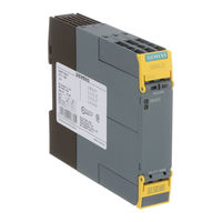
SIRIUS 3RQ1
User Manuals: Siemens SIRIUS 3RQ1 Coupling Relay
Manuals and User Guides for Siemens SIRIUS 3RQ1 Coupling Relay. We have
2
Siemens SIRIUS 3RQ1 Coupling Relay manuals available for free PDF download: Equipment Manual, Original Operating Instructions
Siemens SIRIUS 3RQ1 Equipment Manual (230 pages)
Brand:
Siemens
| Category:
Relays
| Size: 13.59 MB
Table of Contents
Table of Contents
3
1 Introduction
9
Purpose of this Manual
9
Target Group
10
Required Basic Knowledge
11
Validity Range
12
Siemens Industry Online Support
13
Siemens Industry Online Support App
15
Datamatrix Code
16
Configurator for 3SK1 Safety Relays
17
User Responsibility for System Design and Function
18
Additional Documentation
19
History
20
Support Request
21
2 Safety Instructions
23
General Safety Notes
23
Recycling and Disposal
26
Intended Use
27
Current Information about Operational Safety
28
Security Information
29
Electromagnetic Compatibility (EMC) According to IEC 60947-5-1
30
3 Description
31
Use
31
Product Overview
32
Components and Accessories
34
Functional Scope of the 3SK1 Basic Units
35
3SK1 System
36
3SK1 Standard System Configuration
36
3SK1 Advanced System Configuration
37
4 Safety Systems - General Information
41
What Is Safety
41
Safety Function
42
Basic Terminology
43
Redundancy/Single-Channel and Two-Channel
43
Cross-Circuit Detection
44
Enabling Circuit (Safety-Related Output)
44
Signaling Circuit
44
Feedback Circuit
45
Stop Category 0
45
Automatic Start
46
Manual Start
46
Monitored Start
46
Two-Hand Operation/Synchronism
47
Cascading
48
Startup Testing
48
Connection of Actuators
48
Series Connection of Sensors
51
Use of Magnetically Operated Switches
52
3 SK1 / 3RQ1 Devices
53
3SK1 Standard
53
General Information
53
Applications
53
3SK1111 Standard Basic Unit Instantaneous (with Relay Outputs)
54
General Information
54
Function Description
54
Design
55
Terminal Assignment
55
Inputs
56
Outputs
57
Display of the Operating State
57
Function Setting
57
3SK1112 Standard Basic Unit Instantaneous (with Semiconductor Outputs)
60
General Information
60
Function Description
61
Design
62
Terminal Assignment
62
Inputs
63
Outputs
64
Display of the Operating State
64
Function Setting
64
3SK1 Advanced
67
General Information
67
Applications
67
General Device Features
67
Function Description
68
Functions
69
3SK1121 Advanced Basic Unit Instantaneous (with Relay Outputs)
70
Device Features
70
Function Description
70
Design
71
Terminal Assignment
71
3SK1121 Advanced Basic Unit Time-Delayed (with Relay Outputs)
73
Device Features
73
Design
74
Terminal Assignment
74
3SK1122 Advanced Basic Unit Instantaneous (with Semiconductor Outputs)
76
Device Features
76
Design
78
Terminal Assignment
78
3SK1122 Advanced Basic Unit Time-Delayed (with Semiconductor Outputs)
80
Device Features
80
Design
82
Terminal Assignment
82
3SK1120 Advanced Basic Unit Instantaneous (with Semiconductor Outputs)
84
Device Features
84
Design
86
Terminal Assignment
86
Status Diagrams
87
3SK1 Output Expansions
89
Applications
89
Function Description
89
Display of the Operating State
90
Function Setting
90
Output Expansion 3SK1211
90
Device Features
90
Design of 3SK1211-.B..0
92
Design of 3SK1211-.BB40
93
Terminal Assignment
93
Output Expansion 3SK1213
94
Device Features
94
Design of 3SK1213-.AB40
95
Design of 3SK1213-.A.20
96
Terminal Assignment
96
3RM1 Failsafe Motor Starters
97
3RQ1 Output Expansion
98
Applications
98
Function Description
99
Display of the Operating State
99
Device Features
99
3RQ11.00-.E.00, 3RQ1000-.G.00 Configuration
101
3RQ1000-Xhb00, 3RQ1000-Xlb00 Configuration
102
Terminal Assignment
102
3SK1 Input Expansions
104
Input Expansion 3SK1220
104
Device Features
104
Applications
104
Design
105
Terminal Assignment
105
Display of the Operating State
106
Function Setting
106
Power Supply 3SK1230
107
Device Features
107
Applications
108
Design
109
Terminal Assignment
109
Display of the Operating State
110
6 System Configuration
111
General Information
111
General Notes on the Standard System
111
General Information on the Advanced System
111
Maximum System Configuration
112
3ZY12 Device Connector
116
Device Features
116
Applications
119
System Configuration Rules
120
7 Mounting
123
Warning Notices
123
Terminal Coding
124
Mounting the Devices on a Level Surface
125
Disassembling Devices from a Level Surface
127
Mounting 22.5 MM/17.5 MM Devices on a Standard Mounting Rail
129
Mounting the 90 MM Devices on a Standard Mounting Rail
130
Removing Devices from a Standard Mounting Rail
131
Mounting 22.5 MM/17.5 MM Devices with Device Connectors on a Standard Mounting Rail
132
Removing 22.5 MM/17.5 MM Devices with Device Connectors from a Standard Mounting Rail
135
Mounting 90 MM Devices with Device Connectors on a Standard Mounting Rail
138
7.11 Removing 90 MM Devices with Device Connectors from a Standard Mounting Rail
141
Mounting 22.5 MM/17.5 MM Devices with Device Connectors on the Wall
144
7.13 Removing 22.5 MM/17.5 MM Devices with Device Connectors from the Wall
147
Mounting 90 MM Devices with Device Connectors on the Wall
149
Removing 90 MM Devices with Device Connectors from Wall
152
Mounting the Sealable Cover
154
8 Connection
155
Warning Notices
155
22.5 MM/17.5 MM Devices
156
Terminal Assignment
156
Connection Data for 3SK1 Terminals
157
Connection Data for 3RQ1 Terminals
158
Connecting the Screw-Type Terminals
158
Disconnecting the Screw-Type Terminals
159
Wiring Rules for Spring-Loaded Terminal (Push-In System)
160
Connection Data for 3SK1 Spring-Loaded Terminal (Push-In System)
160
Connection Data for 3RQ1 Spring-Loaded Terminal (Push-In System)
161
Connecting Spring-Loaded (Push-In) Terminals
161
Disconnect the Spring-Loaded (Push-In) Terminal
162
Attaching the Terminals
163
Disconnecting
164
Devices 90 MM
167
Opening the Terminal Cover
167
Connection Data for Terminals
168
Connecting Terminals
168
Mounting Terminals
170
Disconnecting
171
Device Replacement
173
9 Configuration / Operation
175
Procedure for Configuration
175
Explanation of the Device's Functions
176
Modes
179
Response Times
180
10 Commissioning
183
11 Display and Diagnostics
185
LED Display
185
Power-Up
187
Error Statuses
188
Diagnostics
189
12 Technical Data
191
Technical Data in Siemens Industry Online Support
191
Electrical Endurance
192
Overview Tables
194
13 Dimension Drawings
195
Cax Data
195
14 Circuit Diagrams
197
Cax Data
197
Internal Circuit Diagrams
198
Internal Circuit Diagrams for 3SK1 Standard Basic Units
198
Internal Circuit Diagrams for 3SK1 Advanced Basic Units
200
Internal Circuit Diagrams for Expansion Units
202
Typical Circuits
211
Typical Circuits of 3SK1 Safety Relays with 3RM1 Failsafe Motor Starters
222
3SK1 Safety Relay with 3RM1 Failsafe Motor Starter Via Device Connector
222
3SK1 Safety Relay Wired with 3RM1 Failsafe Motor Starter
224
Additional Applications
226
Advertisement
Siemens SIRIUS 3RQ1 Original Operating Instructions (9 pages)
Force-guided coupling relays
Brand:
Siemens
| Category:
Relays
| Size: 4.45 MB
Advertisement
Related Products
Siemens SIRIUS 3RR2242-2F.30
Siemens 3RV1976-3AP3
Siemens 3RB20
Siemens 3RH21 4
Siemens 3RH24 0LA
Siemens 3RB23
Siemens SIRIUS 3RR24
Siemens SIRIUS 3RR2443-1AA40
Siemens 3RB2483-4AC1
Siemens 3RS2
Siemens Categories
Industrial Equipment
Controller
Control Unit
Oven
Washer
More Siemens Manuals
Login
Sign In
OR
Sign in with Facebook
Sign in with Google
Upload manual
Upload from disk
Upload from URL