Sign In
Upload
Manuals
Brands
IBM Manuals
Storage
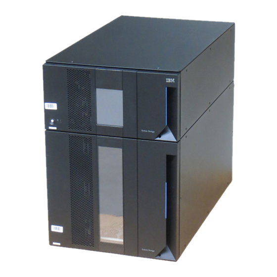
System Storage TS3310
IBM System Storage TS3310 Tape Library Manuals
Manuals and User Guides for IBM System Storage TS3310 Tape Library. We have
5
IBM System Storage TS3310 Tape Library manuals available for free PDF download: Maintenance Information, Setup And Operator Manual, Update Manual, Product Manual
IBM System Storage TS3310 Maintenance Information (531 pages)
System Storage Tape Library
Brand:
IBM
| Category:
Storage
| Size: 10.92 MB
Table of Contents
Registering for Support Notification
5
Sending Us Your Comments
5
7Th Edition
7
Summary of Changes
7
Table of Contents
9
Figures
15
Tables
19
Getting Assistance
21
Preface
21
Related Publications
21
Chapter 1. Start Service
23
Chapter 2. Product Description
29
Front Panel Components
30
Front Panel of a 14U Library
30
Control Module (3576 Model L5B)
31
Expansion Module (3576 Model E9U)
31
I/O Station
31
Library I/O Station Configurations
31
Access Door
32
Operator Panel
32
Power Button
32
Front Panel Leds
32
Rear Panel Components
33
Library Control Blade (LCB)
33
Rear Panel of a 14U Library
33
Tape Drives
34
Power Supply
35
Interior Components
35
Storage Columns
36
Robot Assembly Designs
36
Optional Features
38
M2 Label on the M2 Robot Assembly
38
Power Supply
38
Ultrium Tape Drives
39
Ultra160 SCSI Tape Drives in the Library
39
Redundant Power Supply (Feature Code 1900)
40
Feature Licenses
40
Licensable Cartridge Slots (Storage and I/O)
48
Location Coordinates
51
Modules
52
Columns
52
Library Location Coordinates
52
Slots
53
Drives
53
Power Supplies
53
Drive Location Coordinates
53
Data Cartridges
54
Power Supply Location Coordinates
54
Ultrium Cartridge
55
Environmental and Shipping Specifications for Tape Cartridges
56
Environment for Operating, Storing, and
56
Multi-Path Architecture
57
Using Multiple Control Paths
57
Using Multiple Data Paths for Data Path Failover
57
Lightweight Directory Access Protocol (LDAP)
58
Specifications
59
Physical Specifications for the Library
59
Library Component Weight
59
Power Specifications for a 5U Control
59
Product Environment
60
Maintenance Plan
60
Other Specifications for the Library
60
Environmental Specifications for the Library
60
Maintenance Start
61
Supported Servers, Operating Systems, and Software
61
Supported Device Drivers
61
Chapter 3. Library Components
63
14U Library, Front View, I/O Station Door Open
64
Library Rear View
64
Front View of a 14U Library with the I/O Station Door Open
64
I/O Station Lock Assembly
65
Rear View of a 14U Library
65
I/O Station Lock Assembly Installed in the Library
65
I/O Station with Slide Assembly
66
Access Door, Inside, with Operator Panel
67
Access Door Open Showing Back of
67
Gear Rack
68
Y-Axis/Picker Assembly and M2 Robot Assembly
68
Original Y-Axis/Picker Assembly
69
M2 Robot Assembly
69
Home Sensor Flag
70
Cable Spool Assembly
71
Cable Spool Assembly Components
71
Library Control Blade (LCB)
72
Compact Flash Card on LCB
73
Library Control Blade and Compact Flash
73
Power Supply
74
Drive Sleds, Rear Panel
75
LTO 3 Drive Sleds
75
Chapter 4. User Interfaces
77
Operator Panel
77
Operator Panel Login Screen
77
Operator Panel Login Screen for Firmware
77
Common Operator Panel Elements
79
Operator Panel Common Header Elements
79
Keyboards
80
Home Page
80
Home Screen Capacity View
80
Menus Available from the Operator Panel
81
Operations Menu Screen
82
Web User Interface (UI)
83
Tools Menu Screen
83
Tape Library Operator Panel Menu Tree
83
Logging in to the Web User Interface
84
Common Header Elements
84
Menus Available from the Web User Interface
84
Menus Available from the Web User
84
User Privileges
86
System Functions, Commands, and Access
86
View
87
Display
87
View
88
Drive
88
View)
89
Removed)
89
Cartridge
89
Chapter 5. Safety and Environmental Notices
93
Safety Notices
93
Possible Safety Hazards
94
Class I Laser Product
95
Protective Devices
95
Rack Safety
96
Power Cords
97
Product Recycling and Disposal
98
Battery Return Program
99
Removing a Battery from a Snaphat Battery Holder
101
Monitor Recycling or Disposal
101
Snaphat Battery Holder
101
Chapter 6. Service Action Tickets (Txxx) and Diagnostic Resolutions (Drxxx)
103
Service Action Tickets
103
T001: Tape Cartridge Stuck in Picker, Motion OK
103
T002: PUT Operation Failed, Final Cartridge Position Unknown, Motion OK
104
T003: GET Operation Failed, Final Cartridge Position Unknown, Motion OK
105
T004: PUT Operation Failed, Tape Back in Source Location, Motion OK
105
T005: X, Y, Θ Motion Profile Failure, Tape in Picker, Motion NOT OK
106
T006: X, Y, Θ Motion Profile Failure, no Tape in Picker, Motion NOT OK
107
T007: X, Y, Θ Motion Obstruction, Motion OK
107
T008: Cannot Home, Motion OK
108
T009: Drive Load Unsuccessful, Motion OK
109
T010: Drive Unload Failed
109
T011: Drive over Eject Condition
110
T012: Drive Unload Control Prevented
110
T013: Invalid Library SN Label, Library Cannot Initialize
111
T014: I/O Station Magazine Missing
111
T015: Drive Sled Fiducial Read Failure
112
T016: Unexpected Drive Type
112
T017: Invalid Storage or I/O Position
113
T018: Invalid Drive Position
113
Calibration Sensor
113
T019: Drive Calibration Failure, Motion OK
114
T020: Storage Calibration Failure, Motion OK
114
T021: Drive Sled Communication Failure
115
T022: Tape Drive Communication Failure
116
T023: Drive Sled Fan Failure
116
T024: AC Power Loss
116
T025: Power Supply Hardware Failure
117
T026: Primary Key Server Failover
117
T027: Key Server Communication Failure
118
T028: Secondary Key Server Failover
118
T029 - Key Server Communication Warning
119
T030: Excessive I/O Station Events
119
T031: I/O Station Unlock Failure
120
T032: I/O Station Lock Failure
120
T033: Drive Tapealert Flag 3 - Hard Read or Write Error
121
T034: Drive Tapealert 4 - Media Error
121
T035: Drive Tapealert Flag 5 - Read Failure
121
T036: Drive Tapealert Flag 6 - Write Failure
122
T037: Drive Tapealert Flag 8 - Not Data Grade
122
T038: Drive Tapealert Flag 9 - Write Protected
122
T039: Drive Tapealert 12 - Unsupported Format
123
T040: Drive Tapealert 15 - MIC Chip Failure
123
T041: Drive Tapealert 16 - Forced Eject
123
T045: Drive Tapealert 20 - Clean Now
124
T046: Drive Tapealert 21 - Clean Periodic
124
T047: Drive Tapealert 22 - Expired Cleaning Media
124
T048: Drive Tapealert 23 - Invalid Cleaning Tape
125
T049: Drive Tapealert 30 - Hardware a
125
T050: Drive Tapealert 31 - Hardware B
126
T051: Drive Tapealert 32 - Interface
126
T052: Drive Tapealert 33 - Media Eject Required
127
T053 - Unload Timeout
127
T055: Drive Tapealert 37 - Drive Detects Voltage Problem
128
T060: Main Access Door Open
128
T061: Tape Alert 55 - Loading Fail
129
T062: Module Configuration Problem
129
T063: WWNN Label Change
130
T064: LCB Hardware Failure
131
T065: Robot over - Current Condition
131
T066: Drive Power Fuse (F1) Blown
132
T067: Display Assembly Hardware Failure
132
T068: Destination Element Full
133
T069: Source Element Empty
133
T070: Library Control Path Failure
134
T071: Missing Power Supply
134
T072: Unmanaged System Fault
135
T073: I/O Storage Door Open
135
T074: Drive Sled Auto-Leveling Failure
135
T075: Unsupported Module Configuration
136
T076: Robot Initialization Failure
136
T077: I/O Station Partially Partially Open
137
T079: Get Operation Failed, Motion OK
137
T080: Module SN Change
138
T081: Incorrect Module Brand
138
T082: Volume Serial Scanner Failure
139
T083: Unlevel Robot Assembly Not Level
140
T084: Missing Cleaning Tape
141
T085: Unknown Cartridge in Cleaning Slot
141
T086: Inaccessible Tape Cartridge
142
Cartridge
142
T087: Invalid Library SN Label Warning
143
T089: E-Mail Notification Error
144
T090: Invalid Cleaning Tape
144
T091: Tape Alert 56 - Unload Failure
145
T092: Unreadable Branding Identifier
145
T093: Automatic Cleaning Failure
146
T094: Drive Bay Open
146
T095: Installation and Verification Test (IVT) Failure
146
T096: Module Communication Error
147
T108: Incompatible Drive Brand
147
T109: Drive Firmware Update Failure
148
T110: Drive Firmware Mismatch Detected
148
T112: Invalid Tape Drive Firmware Image
149
T114: Unassigned Tape Cartridge
149
T115: Installation & Verification Test Warning
149
T116: Robotics Firmware Image Error
150
T117: Robotics Auto-Level Failure
150
T118: Degraded Robotics Flash
150
T120: Robotics Y-Axis Motion Failure, Tape in Picker
151
T121: Robotics Y-Axis Motion Failure, no Tape in Picker
151
T122: Robotics X, Z, Theta Axis Motion Failure, Tape in Picker
152
T123: Robotics X, Z, Theta Axis Motion Failure, no Tape in Picker
152
T124: Robotics Hardware Error - RCB
153
T125: Robotics Hardware Error - Picker
153
T126: Robotics Hardware Error - Scanner
153
T127: Robotics Communication Error
154
T128: Incompatible Robot Installation
154
T129: Drive Sled Firmware Image Error
155
T130: Tape Drive Cleaning Failure
155
T132: Hardware Clock Failure
155
T133: Barcode Label Mapping Failure
155
T134: Barcode Scanner Malfunction
156
T135: Tape Drive Type Change
156
T136: Robotics Z Axis Motion Failure
157
T137: Display Assembly Communication Failure
157
T139: Robotics Communication Loss
158
T141: Unknown Picker Calibration Offsets
158
T142: Robotics Y-Axis Hardware Failure
159
T143: Unlabeled Cartridge Detected
159
T144: I/O Station Door Sensor Stuck
160
T145: Media Removal Notification
160
T146: Media Removal Warning
160
T149: Key Path Diagnostic Delay
161
T153: Drive Encryption Control Failure
161
T154: Drive Encryption Monitoring Warning
161
Diagnostic Resolutions
162
DR001: Resolve Picker Cartridge Presence
162
DR002: Resolve Tape Cartridge Recovery
162
DR003: Resolve Drive Eject Failure
163
DR004: Resolve Full Destination Element
163
DR005: Resolve Motion Failure
164
DR006: Drive Diagnostic (a Library Verify Test)
164
DR007: Resolve Barcode Scanner Issue
165
DR008: Resolve Stuck I/O Station Interrupt
165
DR009: Resolve AC Failure
165
DR010: Termination and Connectivity Diagnostic
166
DR011: Resolve I/O Station Lock/Unlock Failure
166
DR012: Resolve Drive Tape Alert 32 - Host Interface
167
DR014: Resolve Write-Protected Tape Cartridge
168
DR015: Resolve Unsupported Tape Format
168
DR016: Resolve Prevent/Allow Media Removal
169
DR018: Resolve Drive Cleaning Requirement
169
DR019: Resolve Open Access Door
169
DR020: Resolve Library Inventory Mismatch
170
DR021: Contact IBM Service
170
DR022: Resolve Missing Power Supply
170
DR023: Resolve Missing I/O Station Magazine
171
DR024: Close I/O Door
171
DR025: Resolve Stuck I/O Station Sensor
171
DR026: Resolve Unsupported Module Configuration
172
DR027: Resolve Unknown Library SN Label
172
DR028: Resolve Motion Obstruction
173
DR029: Resolve Drive Sled Communication Loss
173
DR030: Resolve Drive Load Failure
174
DR031: Resolve Robot Initialization Failure
174
DR032: Resolve Drive Control Path Failure
175
DR033: Resolve Drive Sled Auto-Level Failure
175
DR034: Resolve Open Storage I/O Door
175
DR035: Resolve Robot Power Interruption
176
DR036: Resolve Partially Open I/O Station
176
DR037: Resolve Media Eject
177
DR039: Resolve Logical Library Deletion
177
DR040: Resolve Incompatible Module Branding
177
DR041: Resolve Robot Installation
178
DR042: Resolve Missing Cleaning Cartridge
178
DR043: Resolve Invalid Cleaning Cartridge
179
DR044: Resolve Drive Tapealert 4 - Media Error
179
DR045: Resolve Drive Tapealert 5, 6 - Read/Write Failure
179
DR046: Resolve Drive Tapealert 8 - Suspect Data Grade Tape
180
DR047: Resolve Drive Tapealert 15 - Cartridge Memory Failure
180
DR048: Resolve Drive Tapealert 16 - Forced Eject
180
DR049: Resolve Drive Tapealert 30, 31 - Drive Hardware Error
181
DR050: Resolve Invalid Tape Location
181
DR051: Resolve Library SN Label Detection
181
DR053: Resolve Network Configuration Issue
182
DR054: Resolve Open Drive Bay
182
DR055: Resolve Installation & Verification Test Error
182
DR056: Resolve Module Communication
182
DR068: Resolve Incompatible Tape Drive
183
DR069: Resolve Drive Firmware Update Failure
183
DR070: Resolve Tape Drive Firmware Mismatch
183
DR072: Resolve Tape Drive Auto-Level Failure
184
DR074: Resolve Unassigned Inaccessible Tape Cartridge
184
DR075: Resolve Installation & Verification Test Warning
184
DR076: Resolve Get Failure
184
DR077: Resolve Invalid Cleaning Tape
185
DR078: Resolve Tape Load/Unload Failure
185
DR079: Resolve Key Server Communication Issue
185
DR080: Resolve Unreadable Branding
186
DR081: Resolve Autoclean Failure
186
DR082: Resolve Library Calibration Failure
186
DR083: Resolve Drive Voltage Problem
188
DR084: Resolve Robotics Firmware Image Error
188
DR085: Resolve Robotics Auto-Level Failure
188
DR086: Resolve Robotics Degraded Flash Warning
188
DR088: Resolve Robotics Y-Axis Motion Failure
189
DR089: Resolve X, Z, Theta Axis Motion Failure
189
DR090: Resolve Robotics Hardware Error - RCB
189
DR091: Resolve Robotics Hardware Error - Picker
189
DR092: Resolve Robotics Hardware Error - Scanner
190
DR093: Resolve Robotics Communication Error
190
DR094: Resolve Incompatible Robot Installed
190
DR095: Resolve Drive Sled Auto-Level Failure
191
DR096: Resolve Drive Cleaning Failure
191
DR098: Resolve Hardware Clock Failure
191
DR099: Resolve Barcode Label Mapping
191
DR100: Resolve Barcode Scanner Malfunction
192
DR101: Resolve Tape Drive Type Change
192
DR102: Resolve Robotics Z Axis Motion Failure
192
DR103: Resolve Display Assembly Communication Failure
193
DR105: HPF Connection Failure
193
DR106 - Resolve Media Security Notification
193
DR110: Resolve Drive Encryption Control Failure
194
DR111: Resolve Drive Encryption Service Request Monitoring
194
DR118 - Resolve EKM Path Diagnostic Delay
195
Advertisement
IBM System Storage TS3310 Setup And Operator Manual (345 pages)
Tape Library
Brand:
IBM
| Category:
Storage
| Size: 14.39 MB
Table of Contents
Contacting IBM Technical Support
5
Registering for My Support
5
Sending Us Your Comments
5
Summary of Changes, 2Nd Edition
5
Summary of Changes, 3Rd Edition
6
Table of Contents
7
Figures
13
Caution Notice
17
Danger Notice
17
Safety and Environmental Notices
17
Class I Laser Product
18
Laser Safety and Compliance
18
Monitored Access to the Library
18
Possible Safety Hazards
18
Protective Devices
18
Main Power Switch
19
Rack Safety
19
Power Cords
21
Disposal of Library Components Containing Mercury
22
European Directive about Product Recycling and Disposal
22
Battery Return Program
23
Intended Audience
25
Preface
25
Related Publications
25
Chapter 1. Product Description
27
Tape Cartridge
27
Front Panel Components
28
Control Module (3576 Model L5B)
28
Front Panel of a 14U Library
28
Expansion Module (3576 Model E9U)
29
I/O Station
29
Access Door
29
Library I/O Station Configurations
29
Operator Panel
30
Power Button
30
Front Panel Leds
30
Rear Panel Components
31
Library Control Blade (LCB)
31
Tape Drives
31
Rear Panel of a 14U Library
31
The Library Control Blade
31
Power Supply
32
Interior Components
32
Storage Columns
33
Robotic System
33
Robotic System of the Library
33
Optional Features
34
Ultrium 3 Tape Drives
34
SCSI Ultrium 3 Tape Drives in the Library
34
Redundant Power Supply (Feature Code 1900)
35
Feature Licenses
35
Licensable Cartridge Slots (Storage and I/O) Per Model
36
Library & Drive Code Update (Feature Code 0500)
38
Location Coordinates
38
Modules
39
Columns
39
Slot 1
39
Module
39
Slots
40
Drives
40
Power Supplies
40
Drive Location Coordinates
40
Media
41
Environmental and Shipping Specifications for Tape Cartridges
41
Multi-Path Architecture
42
Specifications
42
Physical Specifications for the Library
42
Library Component Weight
42
Environment for Operating, Storing, and
42
Product Environment
43
Power Specifications for a Maximum
43
Other Specifications for the Library
43
Environmental Specifications for the Library
43
Supported Servers, Operating Systems, and Software
44
Supported Device Drivers
44
Chapter 2. Installation Planning
47
Determining the Number of Logical Libraries (Partitions)
47
Basic Guidelines
47
Library Sharing
47
Using Multiple Logical Libraries for Library Sharing
48
Using Multiple Control Paths
48
Using Multiple Control Paths for System I
49
Using Multiple Control Paths for Control Path Failover
49
Using Multiple Data Paths for Data Path Failover
49
Determining SCSI and Fibre Channel Ids
50
SCSI Drive Ids
50
Module
50
Default SCSI ID for each SCSI Drive in a 14U Library
50
Fibre Channel Drive Ids
51
Default Loop Ids and Their Associated
51
Choosing the Port for Your Topology and
53
Server Attachment
54
SCSI Interface
54
Maximum Bus Length between Terminators
54
Recommended Maximum Quantity of Drives
55
Fibre Channel Interface
56
Chapter 3. Installing a New Library in a Rack
59
Unpacking and Verifying Shipment Contents
59
Shipment Contents
59
Shipment Contents
60
Library with Internal Packaging Material
61
Yellow Ribbon-Like Packing Pieces
62
Reducing Weight
63
Removing a Power Supply
63
Library Packaging Material Pieces
63
Removing a Drive Sled
64
Preparing the Library Module(S) for Installation
65
SCSI Drive Sled (Detail)
65
Transferring the Bottom Cover from the Control Module to an Expansion Module
66
Picker Locking Mechanism
66
Bottom Cover of the 5U Control Module
67
Home Sensor on Inner Side of Bottom Cover
68
Bottom View of Picker Assembly Lock
68
Transferring the Top Cover from the Control
69
Picker Locking Mechanism
69
Verifying Rack Mount Kit Contents
70
Top Cover of the 5U Control Module
70
Rack Mount Kit Contents
71
Identifying the Location in the Rack
72
Additional Rack Hardware Kit Contents (Included with each Expansion Module)
72
EIA Identification and Rail Stud Locations
74
EIA Identification and Rail Stud Locations for REAR Vertical Rack Rails
75
Installing the Rails
76
EIA Identification and Rail Stud Locations
76
Rails Installed in Rack (Front View)
77
Rails Installed in Rack (Rear View)
78
Installing the Bottom Library Module in a Rack
79
Sling Handles Folded Properly
80
Installing Additional Modules in Your Library Configuration
81
Rear Flange and Thumb Screw on Rack Rail
81
Picker Assembly Lock Mechanism
82
Module-To-Module Alignment Pin and Front
83
Thumb Screw
84
Installing the Rack Ears
85
Enabling the Picker Assembly
86
Installing the Rack Ears on a Control
86
Installing Library Components Removed for Weight Reduction
87
Releasing the Picker Assembly Lock
87
Replacing a Drive Sled
88
Control Module
88
Guide Rails and Guide Slots Inside a Drive
88
Replacing a Power Supply
89
Cabling the Library
90
Cabling a 5U Control Module
90
Control Module Power Supply
90
Cabling with Fibre Channel Drives
90
Cabling with SCSI Cables
91
Cabling of a 5U Library with Fibre Drives
91
Cabling of a 14U Library Containing
92
Cabling with Fibre Channel Drives
93
Cabling with Fibre Channel Drives
94
Powering on the Library
95
Chapter 4. Installing a New Standalone Library on a Desktop
97
Unpacking and Verifying Shipment Contents
97
Library with Internal Packaging Material
99
Yellow Ribbon-Like Packing Pieces
100
Reducing Weight
101
Removing a Power Supply
101
Library Packaging Material Pieces
101
Removing a Drive Sled
102
Choosing a Desktop Configuration
103
SCSI Drive Sled (Detail)
103
Transferring the Bottom Cover from the Control
104
Module to an Expansion Module
104
Recommended Desktop Library Configurations
104
Bottom Cover of the 5U Control Module
106
Home Sensor on Inner Side of Bottom Cover
107
Bottom View of Picker Assembly Lock
107
Installing Library Foot Pads
108
Transferring the Top Cover from the Control
108
Module to an Expansion Module
108
Foot Pad Locations
108
Installing Additional Modules in Your Library
110
Configuration
110
Picker Assembly Lock Mechanism
110
Module-To-Module Alignment Pin and Front Thumb Screw
111
Enabling the Picker Assembly
113
Installing Library Components Removed for Weight Reduction (for Rack Installations Only)
114
Replacing a Drive Sled
114
Releasing the Picker Assembly Lock
114
Control Module Drive Sled
115
Guide Rails and Guide Slots Inside a Drive
115
Replacing a Power Supply
116
Cabling the Library
117
Cabling a 5U Control Module
117
Control Module Power Supply
117
Cabling with SCSI Cables
118
Cabling of a 5U Library with Fibre Drives
118
Cabling of a 14U Library Containing
119
Cabling with Fibre Channel Drives
120
Powering on the Library
122
Chapter 5. Configuration Planning
123
Understanding Cartridge Assignment in the Library
123
Modifying Network Settings
123
Applying a License Key
124
Cleaning Slots Configuration
124
Host-Based Cleaning of a Drive
125
Configuring I/O Stations
125
Selecting Drive Ids and Drive Types
125
Working with Logical Libraries
126
Automatically Creating Logical Libraries
126
Manually Creating Logical Libraries
127
Deleting Logical Libraries
127
Changing Logical Library Access
127
Changing Logical Library Modes
127
Working with User Accounts
128
Creating User Accounts
128
Modifying User Accounts
129
Deleting User Accounts
129
Chapter 6. User Interfaces
131
Operator Panel
131
Common Operator Panel Elements
132
Operator Panel Common Header Elements and Subsystem Status Buttons
132
Keyboards
133
Login Screen
133
Operator Panel Login Screen
133
Home Page
134
Menus Available from the Operator Panel
134
Home Screen Capacity View
134
Setup Menu Screen
135
Operations Menu Screen
135
Tools Menu Screen
136
Web User Interface (UI)
137
Logging in to the Web User Interface
137
Common Header Elements
138
Menus Available from the Web User Interface
138
User Privileges
139
Control Panel Commands and Access
140
Web User Interface Menu Commands and Access
141
Chapter 7. Configuring the Library
143
Step 1: Log in to the Operator Panel
144
Operator Panel Log in Screen
144
Step 2: Access the Setup Wizard
145
Step 3: Ensure that All Hardware Is Installed
145
Step 4: Set up the Library Network Configuration
145
Step 5: Enter License Keys
146
Step 6: Assign Cleaning Cartridge Slots
146
Step 7: Assign I/O Station Slots
147
Step 8: Assign Logical Libraries
147
Step 9: Set the Date and Time
147
Step 10: Insert Cleaning Cartridge(S)
148
Step 11: Populate Your Library with Data Cartridges
148
Step 12: Register for My Support
149
Chapter 8. Operating Procedures
151
Library and Logical Libraries
152
Viewing System Information
152
Viewing Library Map
152
Accessing the Setup Wizard
152
Library Verify Diagnostic Tests
152
Creating Logical Libraries
153
Deleting/Modifying a Logical Library
153
Assigning Cleaning Slots
154
Assigning I/O Station Slots
154
Entering License Keys
154
Creating Users Accounts
154
Modifying/Deleting User Accounts
155
Viewing and Setting LDAP Parameters
155
Setting DNS Parameters
156
Setting the Date and Time
156
Setting up Email Notifications
156
Resetting the Library Control Blade IP Address
157
Managing the Network (SSL, Trap Registration, and SNMP Version)
157
Configuring the Library for Remote Access
159
Taking a Logical Library Offline/Online
159
Shutting Down/Restarting the Library
159
Viewing Error Messages
161
Capturing a Library Snapshot
161
Viewing Library Information
161
Locking/Unlocking the I/O Station
162
Firmware Upgrades
162
Updating Library Firmware
162
Updating Drive Firmware
163
Drives
165
Viewing Drive Information
165
Loading a Drive
165
Unloading a Drive
165
Taking a Drive Offline/Online
166
Adding a Control Path Drive to a Logical Library
166
Assigning Drive Ids
166
Modifying a Fibre Channel Drive Port Setting
166
Capturing a Drive Dump
167
Cartridges
167
Inserting Data Cartridges
167
Removing a Data Cartridge
167
Moving Data Cartridges
168
Inserting a Cleaning Cartridge
168
Removing a Cleaning Cartridge
168
IBM System Storage TS3310 Setup And Operator Manual (275 pages)
Tape Library
Brand:
IBM
| Category:
Tape Deck
| Size: 13.13 MB
Table of Contents
Table of Contents
7
Contacting IBM Technical Support
5
Table of Contents
7
Registering for My Support
5
Sending Us Your Comments
5
Figures
11
Tables
13
Caution Notice
15
Danger Notice
15
Possible Safety Hazards
15
Safety and Environmental Notices
15
Class I Laser Product
16
Laser Safety and Compliance
16
Main Power Switch
16
Monitored Access to the Library
16
Protective Devices
16
Rack Safety
17
Power Cords
19
Disposal of Library Components Containing Mercury
20
Product Recycling and Disposal
20
Battery Return Program
21
Cable Warning
21
Intended Audience
23
Preface
23
Related Publications
23
Chapter 1. Product Description
25
Slot
25
Front Panel Components
26
Front Panel of a 14U Library
26
Library Configurations
26
Maximum Capacities of Library
26
Access Door
27
Control Module
27
Expansion Module
27
I/O Station
27
Front Panel Leds
28
Operator Panel
28
Power Button
28
Library Control Blade (LCB)
29
Rear Panel Components
29
Rear Panel of a 14U Library
29
Tape Drives
29
Interior Components
30
Power Supply
30
Robotic System
31
Robotic System of the Library
31
Storage Columns
31
Optional Features
32
SCSI Ultrium 3 Tape Drives in the Library
32
Ultrium 3 Tape Drives
32
Feature Licenses
33
Redundant Power Supply (Feature Code 1900)
33
Library Configurations
34
Licensable Cartridge Slots (Storage and I/O) Per Model
34
Library & Drive Code Update (Feature Code 0500)
35
Location Coordinates
35
Columns
36
Module
36
Modules
36
Drive Location Coordinates
37
Drives
37
Power Supplies
37
Slots
37
Environmental and Shipping Specifications for Tape Cartridges
38
Media
38
Power Supply Location Coordinates
38
Environment for Operating, Storing, and
39
Library Component Weight
39
Multi-Path Architecture
39
Physical Specifications for the Library
39
Specifications
39
Environmental Specifications for the Library
40
Other Specifications for the Library
40
Power Specifications for a Maximum
40
Product Environment
40
Supported Device Drivers
41
Supported Servers, Operating Systems, and Software
41
Chapter 2. Installation Planning
43
Determining the Number of Logical Libraries (Partitions)
43
Basic Guidelines
43
Library Sharing
43
Using Multiple Logical Libraries for Library Sharing
44
Using Multiple Control Paths
44
Using Multiple Control Paths for Iseries and AS/400
45
Using Multiple Control Paths for Control Path Failover
45
Using Multiple Data Paths for Data Path Failover
45
Determining SCSI and Fibre Channel Ids
46
SCSI Drive Ids
46
Fibre Channel Drive Ids
46
Module
46
Drive 1
46
Default SCSI ID for each SCSI Drive in the Library
46
Default Loop Ids and Their Associated
47
Choosing the Port for Your Topology and Fibre Channel Connection
49
Server Attachment
50
SCSI Interface
50
Maximum Bus Length between Terminators
50
Fibre Channel Interface
51
Recommended Maximum Quantity of Drives Per SCSI Bus
51
Chapter 3. Installing the Library
55
Step 1: Unpacking and Verifying Shipment Contents
55
Step 2: Test the Library
56
Shipment Contents
56
Step 3: Installing Your Library in a Rack
58
Verifying Rack Mount Kit Contents
58
Rack Mount Kit Hardware
59
Rack Mount Kit Contents
59
Identifying the Location in the Rack
60
Additional Rack Hardware Kit Contents
60
EIA Identification and Rail Stud Locations for
61
Installing the Rails
62
Rails Installed in Rack (Front View)
63
Rails Installed in Rack (Rear View)
64
Reducing Library Weight
65
Power Supply
65
Placing the Library in the Rack
66
SCSI Drive Sled (Detail)
66
Installing the Rack Ears
67
Installing the Rack Ears on a Control
67
Installing Library Components Removed for Weight Reduction
68
Control Module
68
Guide Rails and Guide Slots Inside a Drive
68
Step 4: Cabling the Library
70
Cabling a 5U Library Containing Fibre Drives
70
Cabling a 5U Library Containing SCSI Drives
71
Cabling of a 5U Library with Fibre Drives
71
Cabling of a 5U Library with One SCSI
72
Cabling a 14U Library Containing Fibre Drives
73
Cabling of a 14U Library Containing Multiple Fibre Drives
73
Module Communication
73
Cabling a 14U Library Containing SCSI Drives
74
Cabling of a 14U Library Containing Multiple SCSI Drives
74
Communication Cable
74
Ethernet Cable
74
Terminator 2 Module-To-Module
74
Cabling a Library Containing Fibre and SCSI Drives
75
Install a Module Communication Terminator in the Upper Receptacle of the Upper Module of Your Library
75
Install One End of the Module-To-Module Communication Cable
75
Step 5: Powering on the Library
76
Step 6: Configuring the Library
77
Chapter 4. Configuration Planning
79
Understanding Cartridge Assignment in the Library
79
Cleaning Slots Configuration
79
Host-Based Cleaning of a Drive
80
Working with Logical Libraries
80
Automatically Creating Logical Libraries
81
Manually Creating Logical Libraries
81
Deleting Logical Libraries
81
Changing Logical Library Access
81
Changing Logical Library Modes
82
Configuring I/O Stations
82
Applying a License Key
83
Selecting Drive Ids and Drive Types
83
Working with User Accounts
83
Creating User Accounts
84
Modifying User Accounts
84
Deleting User Accounts
84
Modifying Network Settings
84
Chapter 5. User Interfaces
87
Operator Panel
87
Common Operator Panel Elements
88
Operator Panel Common Header Elements
88
Keyboards
89
Login Screen
89
Home Page
89
Operator Panel Login Screen
89
Capacity View Home Screen
90
Menus Available from the Operator Panel
91
Library View Home Screen
91
Operations Menu Screen
92
Tools Menu Screen
93
Web User Interface (UI)
94
Logging in to the Web User Interface
94
Common Header Elements
94
Menus Available from the Web User Interface
95
User Privileges
95
Web User Interface Menus
95
Operator Panel Menu Commands and Access
96
Web User Interface Menu Commands and Access
97
Chapter 6. Configuring the Library
99
Operator Panel Log in Screen
100
Step 1: Log in to the Operator Panel
100
Step 2: Access the Setup Wizard
101
Step 3: Ensure that All Hardware Is Installed
101
Step 4: Set up the Library Network Configuration
101
Step 5: Enter License Keys
102
Step 6: Assign Cleaning Cartridge Slots
102
Step 7: Assign I/O Station Slots
103
Step 8: Assign Logical Libraries
103
Step 9: Set the Date and Time
103
Step 10: Import Cleaning Cartridge(S)
104
Step 11: Populate Your Library with Data Cartridges
104
Step 12: Register for My Support
104
Chapter 7. Operating Procedures
107
Library and Logical Libraries
107
Accessing the Setup Wizard
108
Library Verify Diagnostic Tests
108
Viewing System Information
108
Assigning Cleaning Slots
109
Creating Logical Libraries
109
Deleting/Modifying a Logical Library
109
Assigning I/O Station Slots
110
Creating Users Accounts
110
Entering License Keys
110
Modifying/Deleting User Accounts
110
Managing the Network (SSL, Trap Registration, and SNMP Version)
111
Resetting the Library Control Blade IP Address
111
Setting the Date and Time
111
Configuring the Library for Remote Access
113
Shutting Down/Restarting the Library
113
Taking a Logical Library Offline/Online
113
Capturing a Library Snapshot
115
Viewing Error Messages
115
Viewing Library Information
115
Firmware Upgrades
116
Locking/Unlocking the I/O Station
116
Updating Library Firmware
116
Updating Drive Firmware
117
Drives
119
Loading a Drive
119
Viewing Drive Information
119
Adding a Control Path Drive to a Logical Library
120
Assigning Drive Ids
120
Taking a Drive Offline/Online
120
Unloading a Drive
120
Capturing a Drive Dump
121
Cartridges
121
Exporting a Data Cartridge
121
Importing Data Cartridges
121
Modifying a Fibre Channel Drive Port Setting
121
Exporting a Cleaning Cartridge
122
Importing a Cleaning Cartridge
122
Moving Data Cartridges
122
Advertisement
IBM System Storage TS3310 Update Manual (37 pages)
Cisco MDS 9000 for IBM System Storage Interoperability Matrix
Brand:
IBM
| Category:
Storage
| Size: 0.19 MB
Table of Contents
Interoperability Matrix
1
Table of Contents
3
Ess
4
Additional Information
4
Operating Systems
8
Ds8000
8
Ds6000
13
Ds4000
18
Tape
30
Heterogeneous San Support
37
Nas
37
IBM System Storage TS3310 Product Manual (8 pages)
IBM System Storage Product Guide
Brand:
IBM
| Category:
Storage
| Size: 0.89 MB
Advertisement
Related Products
IBM System Storage TS3100
IBM TS3200Tape Library
IBM System Storage TS3200
IBM System Storage TS3500
IBM TS3400
IBM System Storage TS2240
ibm TS1140
IBM TS1155
IBM TS7610
IBM TS2280
IBM Categories
Server
Desktop
Storage
Laptop
Monitor
More IBM Manuals
Login
Sign In
OR
Sign in with Facebook
Sign in with Google
Upload manual
Upload from disk
Upload from URL