Sign In
Upload
Manuals
Brands
IBM Manuals
Storage
Storwize V7000 2076-212
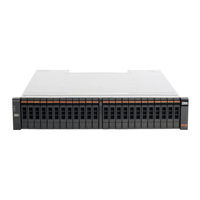
IBM Storwize V7000 2076-212 Enclosure Manuals
Manuals and User Guides for IBM Storwize V7000 2076-212 Enclosure. We have
1
IBM Storwize V7000 2076-212 Enclosure manual available for free PDF download: Problem Determination Manual
IBM Storwize V7000 2076-212 Problem Determination Manual (314 pages)
Brand:
IBM
| Category:
Storage
| Size: 21.12 MB
Table of Contents
Table of Contents
3
Figures
7
Tables
9
Safety
11
Safety and Environmental Notices
11
Safety Statements
13
Sound Pressure
17
About this Guide
19
Emphasis
19
Storwize V7000 Unified Library and Related Publications
19
Storwize V7000 Unified Library
20
Other IBM Publications
21
Who Should Use this Guide
19
How to Order IBM Publications
22
Sending Your Comments
22
IBM Documentation and Related Websites
22
Chapter 1. Storwize V7000 Unified Hardware Components
25
Chapter 2. Best Practices for Troubleshooting
27
Record Access Information
27
Access Information for Your System
27
Follow Power Management Procedures
28
Set up Event Notifications
28
Back up Your Data
29
Manage Your Spare and Failed Drives
29
Resolve Alerts in a Timely Manner
29
Keep Your Software up to Date
30
Keep Your Records up to Date
30
Subscribe to Support Notifications
30
Know Your IBM Warranty and Maintenance Agreement Details
31
Chapter 3. Getting Started Troubleshooting
33
Installation Troubleshooting
34
Problems with Initial Configuration
34
Installation Error Code Actions
36
Installation Error Codes
36
Problems Reported by the CLI Commands During Software Configuration
43
CLI Command Problems
44
Easy Setup Wizard Failure
44
GUI Access Issues
45
Health Status and Recovery
46
Connectivity Issues
48
Host to File Modules Connectivity
48
Rear View of File Module
48
Ethernet Connections Available with the File
49
Ethernet Connectivity between File Modules
49
Ethernet Ports and Type of Connections
50
File Module Node Ethernet Network
50
File Module to Control Enclosure
51
Fibre Channel Connectivity between File Modules and Control Enclosure
54
Diagram Shows How to Connect the File Modules to the Control Enclosure Using Fibre Channel Cables. (A) Is File Module 1 and (B) Is File Module 2. (C) Is the Control Enclosure
55
How to Connect Fibre Channel Cables from File
55
Error Code Port Location Mapping
56
Fibre Channel Cabling from the File Module to the Control Enclosure
57
Fibre Channel Connection on the Node Canister LED State and Associated Actions
57
LED States and Associated Actions. for the Fibre Channel Adapters on the File Module Check the Amber LED Lights Next to the Port
57
Understanding LED Hardware Indicators
58
File Node Hardware Indicators
58
LED Indicators, Corresponding Problem Causes, and Corrective Actions
61
Enclosure Hardware Indicators
66
Leds on the Power Supply Units of the Control
67
Supply Unit
67
Power-Supply Unit Leds
68
Leds on the Node Canisters
69
Power Leds
69
System Status and Fault Leds
69
Management GUI Interface
71
Control Enclosure Battery Leds
71
When to Use the Management GUI
72
Accessing the Storwize V7000 Unified Management GUI
73
Using Fix Procedures
73
Chapter 4. File Module
75
General File Module Procedures
75
Rebooting a File Module
75
Removing a File Module to Perform a Maintenance Action
75
Removing and Replacing File Module Components
77
Hard Disk Drive Problems
80
Selecting a File Module to Display Node Status
82
Displaying Node Status
83
Re-Synchronizing
84
State of Drives
84
Status of Volume
84
Example that Shows that Mirroring Is
85
Example that Shows that a Drive Is Not
86
Example that Shows that the Mirror Is Not Created
87
SMART ASC/ASCQ Error Codes and Messages
90
Monitoring Memory Usage on a File Module
100
Errors and Messages
100
Error Code Information
100
Originating Role Information
100
Understanding Error Codes
100
Ethernet Role and Port Reference
101
Ethernet Switch Error Code Categories
101
Originating File Module and File Module Specific Hardware Code - Code 0, 2, 4
102
Originating File Module Specific Software Code - Code
102
Storage Enclosure Hardware Code - Code
102
Error Code Break down
103
Understanding Event Ids
104
File Module Hardware Problems
105
Components Identified as Customer Replaceable Units (Crus) and Field Replaceable Units (Frus)
105
Installed
107
Removing the Cover
107
Installing the Cover
108
Removing the Battery
109
Removing and Replacing Parts
105
Tier 1 CRU at Your "Installing the Battery
113
Be Charged for the
114
Service Agreements
115
Removing the DIMM Air Baffle
117
Installing the DIMM Air Baffle
118
Removing the Fan Bracket
119
Installing the Fan Bracket
120
Removing the IBM Virtual Media Key
121
Installing the IBM Virtual Media Key
122
Removing a PCI Riser-Card Assembly
123
Installing a PCI Riser-Card Assembly
124
Removing a PCI Adapter from a PCI Riser-Card Assembly
126
Installing a PCI Adapter in a PCI Riser-Card Assembly
127
Removing a 10-Gbps Ethernet PCI Adapter
129
Removing the Ethernet Adapter
131
Location of the Ethernet Adapter Filler Panel on the Chassis
132
Aligning the Ethernet Adapter Port Connectors
133
Location of the Port Openings on the Chassis
133
Port Connector Alignment
134
Side View of Adapter in the Server
134
Removing the SAS Riser-Card and Controller Assembly
135
Tape-Enabled Server Model
136
Installing the SAS Riser Card and Controller Assembly
137
SAS Riser-Card and Controller Assembly on the 16-Drive-Capable Server Model
137
Controller Retention Brackets on 16-Drive-Capable Server Model
138
SAS Controller Front Retention Brackets
138
Installing the Controller Retention Bracket
139
SAS Riser-Card Assembly on Tape-Enabled Server Model
140
Sliding the Controller Retention Bracket Inward and Pressing the Release Tab
140
Removing the Serveraid SAS Controller from the SAS Riser-Card
141
Installing a Serveraid SAS Controller in the SAS Riser-Card
142
Removing a Hot-Swap Hard Disk Drive
143
Installing a Hot-Swap Hard Disk Drive
144
Removing an Optional Serveraid Adapter Advanced Feature Key
144
Serveraid M1000 Advanced Feature Key and M1015 Adapter
145
Installing an Optional Serveraid Adapter Advanced Feature Key
146
Serveraid M5000 Advanced Feature Key and
146
Serveraid M1000 Advanced Feature Key and M1015 Adapter
147
Removing the Serveraid SAS Controller Battery from the Remote Battery Tray
148
Serveraid M5000 Advanced Feature Key and
148
Disconnecting the Remote Battery Cable
149
Releasing the Battery Retention Clip
149
Installing the Serveraid SAS Controller Battery on the Remote Battery Tray
150
Removing the Battery from the Battery Carrier
150
Connecting the Remote Battery Cable
151
Locating the Posts on the Battery and Battery
151
Removing a CD-RW/DVD Drive
151
Installing the CD-RW/DVD Drive
153
Installing a Memory Module
154
Removing a Memory Module
154
DIMM Locations for the Storwize V7000 Unified System X3650 M2 Server
155
Unified System X3650 M3 Server
155
Removing a Hot-Swap Fan
157
Installing a Hot-Swap Fan
158
System Board Fan Locations
159
System Status with 460-Watt Power Supplies
161
Removing the Operator Information Panel Assembly
163
Installing the Operator Information Panel Assembly
164
Heat-Sink Release Lever
165
Microprocessor Release Latch
166
Aligning the Heat Sink above the Microprocessor
170
Bottom Surface of the Heat Sink
170
Thermal Grease
171
Removing the System Board
173
Installing the System Board
175
Removing the 240 VA Safety Cover
177
Installing the 240 VA Safety Cover
178
VA Safety Cover
178
Setting the Machine Type, Model, and Serial Number
179
VA Safety Cover
179
How to Reset/Reboot Server IMM Interface
180
File Module Software Problems
180
Logical Devices and Physical Port Locations
180
Storwize V7000 Unified Logical Devices and
180
Management Node Role Failover Procedures
181
Hostname and Service IP Reference
182
Checking CTDB Health
184
Management GUI Showing CTDB Status for
185
Checking the GPFS File System Mount on each File Module
186
Identifying Created and Mounted File System Mounts
186
Resolving Problems with Missing Mounted File Systems
187
Resolving Stale NFS File Systems
188
Checking User and Server Authentication Issues
188
Error for "Missing SRV Record in DNS
188
If "Netgroup" Functionality with NIS Is Not Working
189
Possible Client Misconfiguration
189
Trouble Accessing Exports When Server and Client Configuration Are Correct
189
Checking Client Access
190
Checking Network Interface Availability
190
Recovering a GPFS File System
191
Error for "MGMTNODE_REPL_STATE ERROR
192
Database_Replication_Failed
192
Resolving an ANS1267E Error
192
Resolving Issues Reported for Lshealth
192
Resolving Network Errors
193
Resolving Full Condition for GPFS File System
194
Analyzing GPFS Logs
195
Synchronizing Time on the File Modules
195
Chapter 5. Control Enclosure
197
Storwize V7000 System Interfaces
197
Service Assistant Interface
197
Service Command-Line Interface
199
Storage System Command-Line Interface
199
USB Key and Initialization Tool Interface
200
Event Reporting
205
Description of Data Fields for the Event Log
206
Understanding Events
206
Event Notifications
207
Notification Types
208
Power-On Self-Test
208
Understanding Events
208
Understanding the Error Codes
208
Understanding the Battery Operation for the Control Enclosure
209
Viewing Logs and Traces
209
Maintenance Discharge Cycles
210
Understanding the Medium Errors and Bad Blocks
211
Bad Block Errors
212
Resolving a Problem
213
Start Here: Use the Management GUI Recommended Actions
213
Problem: Storage System Management IP Address Unknown
214
Problem: Unable to Connect to the Management GUI
214
Problem: Cannot Create a Clustered Storage System
215
Problem: Unable to Log on to the Storage System Management GUI
215
Problem: Unknown Service Address of a Node Canister
216
Problem: Cannot Connect to the Service Assistant
217
Problem: Management GUI or Service Assistant Does Not Display Correctly
218
Problem: Node Canister Location Error
218
Problem: SAS Cabling Not Valid
218
Problem: Code Not Processed from USB Key
219
Problem: Mirrored Volume Copies no Longer Identical
219
Problem: New Expansion Enclosure Not Detected
219
Procedure: Identifying Which Enclosure or Canister to Service
220
Procedure: Resetting Superuser Password
220
Procedure: Checking the Status of Your System
221
Procedure: Getting Node Canister and System Information Using the Service Assistant
221
Procedure: Getting Node Canister and System Information Using a USB Key
222
Procedure: Understanding the System Status Using the Leds
222
Leds on the Power Supply Units of the Control Enclosure
223
Leds on the Node Canisters
225
Power Leds
225
System Status and Fault Leds
225
Procedure: Finding the Status of the Ethernet Connections
227
Procedure: Deleting a System Completely
228
Procedure: Fixing Node Errors
228
Procedure: Removing System Data from a Node Canister
228
Procedure: Changing the Service IP Address of a Node Canister
229
Procedure: Accessing a Canister Using a Directly Attached Ethernet Cable
230
Procedure: Reseating a Node Canister
230
Leds on the Node Canisters
231
Procedure: Powering off Your System
231
Procedure: Collecting Information for Support
232
Procedure: Rescuing Node Canister Software from Another Node (Node Rescue)
232
Removing and Replacing Parts
232
Preparing to Remove and Replace Parts
233
Replacing a Node Canister
233
Rear of Node Canisters that Shows the
234
Removing the Canister from the Enclosure
234
Replacing an Expansion Canister
235
Rear of Expansion Canisters that Shows the
236
Removing the Canister from the Enclosure
236
Replacing an SFP Transceiver
236
Replacing a Power Supply Unit for a Control Enclosure
238
Directions for Lifting the Handle on the Power
240
Using the Handle to Remove a Power Supply Unit
240
Replacing a Power Supply Unit for an Expansion Enclosure
241
Directions for Lifting the Handle on the Power
244
Using the Handle to Remove a Power Supply Unit
244
Replacing a Battery in a Power Supply Unit
245
Removing the Battery from the Control
248
Releasing the Cable Retention Bracket
249
Replacing a 3.5" Drive Assembly or Blank Carrier
249
Removing the 3.5" Drive
250
Unlocking the 3.5" Drive
250
Replacing a 2.5" Drive Assembly or Blank Carrier
251
Unlocking the 2.5" Drive
251
Removing the 2.5" Drive
252
Replacing a SAS Cable
252
Replacing an Enclosure End Cap
252
Replacing a Control Enclosure Chassis
253
Replacing an Expansion Enclosure Chassis
259
Removing a Rail Assembly from a Rack Cabinet
261
Replacing the Support Rails
261
General Storage System Procedures
262
SAN Problem Determination
262
Ethernet Iscsi Host-Link Problems
263
Fibre Channel Link Failures
263
Recover System Procedure
264
When to Run the Recover System Procedure
264
Fix Hardware Errors
266
Performing System Recovery Using the Service Assistant
267
Removing System Information for Node Canisters with Error Code 550 or Error Code 578 Using the Service Assistant
267
Recovering from Offline Vdisks Using the CLI
269
What to Check after Running the System Recovery
269
Backing up and Restoring the System Configuration
270
Backing up the System Configuration Using the CLI
271
Deleting Backup Configuration Files Using the CLI
273
Chapter 6. Call Home and Remote Support
275
Configuring the Remote Support System
275
Establishing an AOS Connection
275
Chapter 7. Recovery Procedures
279
User ID and System Access
279
Accessing a File Module as Root
279
Recovering from Losing the Root Password
279
Resetting the NAS Ssh Key for Configuration Communications
280
Working with NFS Clients that Fail to Mount NFS Shares after a Client IP Change
281
Working with File Modules that Report a Stale NFS File Handle
282
File Module-Related Issues
282
Restoring System X Firmware (BIOS) Settings
282
Recovering from a Multipath Event
283
Recovering from an NFSD Service Error
284
Recovering from an SCM Error
284
Recovering from an Httpd Service Error
285
Recovering from an Sshd_Data Service Error
285
Recovering from an Sshd_Int Service Error
285
Recovering from an Sshd_Mgmt Service Error
285
Recovering from an Sshd_Service Service Error
286
Control Enclosure-Related Issues
286
Recovering from a 1001 Error Code
286
Recovering When a File Volume Does Not Come Back Online
286
Recovering When File Volumes Come Back Online
286
Restoring Data
288
Restoring Asynchronous Data
288
Restoring Tivoli Storage Manager Data
288
Upgrade Recovery
289
Upgrade Error Codes from Using the
290
Upgrade Error Codes and Recommended Actions
291
Appendix. Accessibility
297
Notices
299
Trademarks
301
Electronic Emission Notices
301
Federal Communications Commission (FCC) Statement
301
Australia and New Zealand Class a Statement
302
Avis de Conformité à la Réglementation D'industrie Canada
302
European Union Electromagnetic Compatibility Directive
302
Industry Canada Compliance Statement
302
Germany Electromagnetic Compatibility Directive
303
International Electrotechnical Commission (IEC) Statement
304
Japan VCCI Council Class a Statement
304
Korean Communications Commission (KCC) Class a Statement
304
People's Republic of China Class a Electronic Emission Statement
304
Russia Electromagnetic Interference (EMI) Class a Statement
304
Taiwan Class a Compliance Statement
305
European Contact Information
305
Taiwan Contact Information
305
Index
307
Advertisement
Advertisement
Related Products
IBM Storwize V7000 2076-112
IBM Storwize V7000 2076-324
IBM Storwize V7000 2076-124
IBM Storwize V7000 2076-224
IBM Storwize V7000 2073-700
IBM Storwize V7000 2076-312
IBM Storwize V7000
IBM Storwize V7000 Unified2073-720
IBM Storwize V7000 Gen2
IBM Storwize V5000 Gen 2 Series
IBM Categories
Server
Desktop
Storage
Laptop
Monitor
More IBM Manuals
Login
Sign In
OR
Sign in with Facebook
Sign in with Google
Upload manual
Upload from disk
Upload from URL