Sign In
Upload
Manuals
Brands
IBM Manuals
Network Storage Server
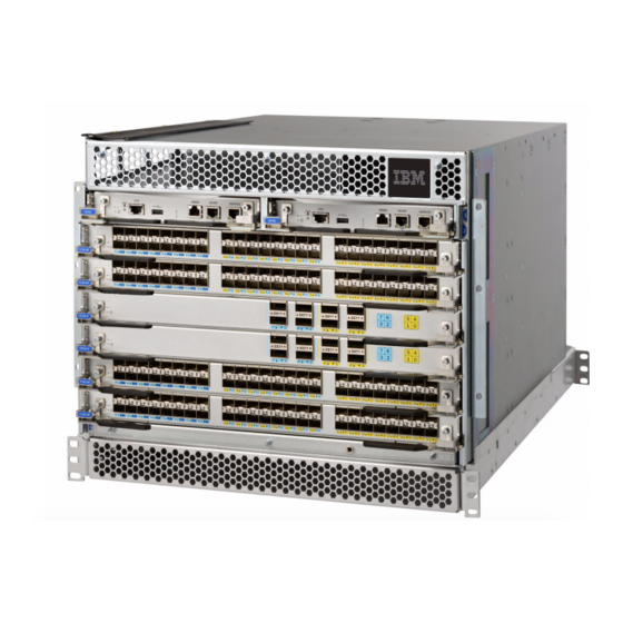
SAN256B-6
IBM SAN256B-6 Manuals
Manuals and User Guides for IBM SAN256B-6. We have
1
IBM SAN256B-6 manual available for free PDF download: Installation, Service And User Manual
IBM SAN256B-6 Installation, Service And User Manual (292 pages)
Storage Networking
Brand:
IBM
| Category:
Network Storage Server
| Size: 16.33 MB
Table of Contents
Table of Contents
3
Figures
7
Read this First
11
Getting Help
11
Accessibility Features
11
How to Send Your Comments
12
Safety and Environmental Notices
13
Safety Notices and Labels
13
Cautions
13
Danger Notices
15
Safety Labels
17
Attention Notices
18
ESD Precautions
19
Rack Safety
19
Rack Installation
19
Rack Relocation (19" Rack)
21
Product Recycling and Disposal
21
What Is New in this Document
23
About this Document
25
Product Documentation
25
Brocade Documents
25
IBM and Brocade Product Matrix
25
Brocade and IBM Product and Model Number
25
Supported Hardware and Software
27
OS-Dependent Frus
27
Rack Mount Kits
28
Introducing the SAN256B-6
29
Product Features
29
Configuration)
29
Hardware Components
30
Port-Side View of Device
31
Port-Side Slot Numbering
32
Nonport-Side View of the Device
32
Nonport Side of the SAN256B-6
33
Preparing for the Installation
35
Safety Precautions
35
Facility Requirements
37
Time and Items Required for Installation
38
Support for 48 Fibre Channel Ports on each FC32-48 Port Blade that Provide 32 Gbps, 16 Gbps
38
Support for 16 Fibre Channel Ports Supporting 4, 8, 16, and 32 Gbps; 16 Gbe Ports Supporting 1 or
38
Quick Installation Checklists
39
Installation Tasks, Time, and Items Required
39
Installation and Basic System Configuration
40
Items Shipped
42
Mounting the Device
43
Mounting Options
43
Mounting Precautions
43
Unpacking and Transporting the Device
45
Installing the 8U Chassis Airflow Diversion or Port Side Exhaust Kit for Four-Post Racks
46
Time and Items Required
46
Installing the Device in an 18-24-Inch Rack
46
Parts List
47
Hardware for Airflow Diversion and Port-Side Exhaust Kit for 18-24 In. (45.72 to 60.96 CM) Racks
47
Airflow Diversion and Port-Side Exhaust Kit Assembly for 18-24 In. (45.72 to 60.96 CM) Racks
48
Torque Requirements
49
Assembling the Rack Hardware
49
Clip and Retainer Nut Locations on Rack Rails
49
Torque Requirements for Mounting Screws
49
Shelf Installed in Rack
51
Installing Air Duct into Side Slot on Shelf
52
Installing the Device in the Rack
53
Securing Top Rail in Rack
53
Installing the Device in a 27-31-Inch Rack
54
Parts List
54
IBM Device with 18-24 In. (45.72 to 60.96 CM) Kit Installed in Rack
54
Airflow Diversion and Port-Side Exhaust Kit Assembly for 27-31 In. (68.58 to 78.74 CM) Racks
55
Hardware for Airflow Diversion and Port Side Exhaust Kit for 27-31 In. (68.58 to 78.74 CM) Racks
55
Torque Requirements
56
Assembling the Rack Hardware
56
Torque Requirements for Mounting Screws
56
Clip and Retainer Nut Locations on Rack Rails
57
Shelf Installed in Rack
58
Installing Air Duct into Side Slot on Shelf
58
Securing Top Rail in Rack
59
Installing the Device in the Rack
60
Device and 27-31 In. (68.58 to 78.74 CM) Kit
60
Installing the 8U Chassis MID-Mount Rack Kit for Two-Post Racks
61
Time and Items Required
61
Parts List
61
Assembling the Rack Hardware
62
Rack Kit Parts
62
Saddle Installed in a Rack
63
Using Clip Nuts and Retainer Nuts to Secure
64
Telco MID-Mount Brackets Installation
64
Installing the Device in the Rack
65
Sliding the Device into the MID-Mount Saddle
65
Installing the 8U Chassis 27-31-Inch Rail Rack Kit for Four-Post Racks
66
Time and Items Required
66
Parts List
67
Rack Kit Parts
67
Assembling the Rack Hardware
68
Device Rails Installed in Equipment Rack
68
Installing the Device in the Rack
69
Using Clip Nuts and Retainer Nuts to Secure
69
Installing a Chassis into the Equipment Rack
69
Removing the Protective Cover
70
Removing Protective Cover from SAN256B-6
71
Initial Setup and Verification
73
Configuration and Verification Task Guide
73
Configuration)
73
Configuration and Verification Tasks
73
Items Required
74
Providing Power to the Device
74
Connecting Power Cord to AC Power Supplies
75
Connecting Power Cord to HVAC/HVDC Power Supplies
76
Using HVAC/HVDC Power Cords
79
Establishing a Serial Connection to the Device
81
Configuring the IP Addresses
82
Establishing an Ethernet Connection to the Device
83
Setting the Domain ID
84
Setting the Date and Time
84
Setting the Time Zone
85
Synchronizing Local Time with an External Source
86
Example: Tstimezone Command Parameter Selection for the US Time Zones
86
Customizing the Chassis and Switch Name
87
Veifying the PID Mode
87
Verifying Installed Licenses and License Key
88
Verifying Correct Operation
88
Backing up the Configuration
89
Powering down the Chassis
90
Installing Transceivers and Cables
93
Supported Transceivers and Cables
93
Port and Extension Blade Transceivers
95
QSFP to QSFP Standard Cables
95
QSFP to SFP Breakout/Cables
95
FC SFP+ Transceiver
96
Optical Transceiver with Bail Open
96
Core Routing Blades
97
QSFP Cable and Transceiver with Bail Open
97
QSFP Transceiver with Separate Cable
97
4X16 Gbps 2 Km LWL QSFP
98
4X32 Gbps 2 Km LWL Qsfps
99
Time and Items Required
99
Precautions Specific to Transceivers and Cables
100
Cleaning the Fiber-Optic Connectors
100
Optical Transceiver Extraction Tool
100
Cable Management
101
Installing an SFP+ Transceiver
101
Installing an SFP+ Transceiver with Pull Tab
102
Installing an SFP+ Transceiver with Bail Latch
102
Replacing an SFP+ Transceiver
103
Replacing a SFP+ Optical Transceiver with Pull Tab into Blade Port
103
Installing a QSFP Transceiver
104
Installing an SFP+ Transceiver with Bail Latch
104
Replacing a QSFP Transceiver
105
Installing a QSFP Transceiver into Blade Port
105
Verifying the Operation of New Transceivers
106
Installing a QSFP Optical Transceiver into Blade
106
Monitoring the Device
109
Interpreting FC32-48 Port Blade Leds
109
FC32-48 Port Blade Leds
109
Port Blade LED Descriptions
110
Interpreting FC32-64 Port Blade Leds
111
Port Blade LED Descriptions
111
FC32-64 Port Blade Leds
112
Interpreting Extension Blade Leds
114
SX6 Extension Blade Leds
114
Extension Blade LED Descriptions
114
Interpreting Control Processor Blade Leds
116
CP Blade LED Descriptions
117
Interpreting Core Routing Blade Leds
118
CR32-4 Core Routing Blade Leds
119
Core Routing Blade LED Descriptions
119
Interpreting WWN Card Leds
120
WWN Card LED Descriptions
120
Interpreting Power Supply Leds
121
Interpreting Fan Assembly Leds
123
Fan Assembly Leds
123
Fan Assembly LED Descriptions
123
Interpreting POST and Boot Results
124
Post
124
Boot
125
Using Monitoring Commands
125
Chassisshow
125
Errdump and Errshow
128
Fanshow
129
Hashow
129
Historyshow
129
Psshow
130
Sensorshow
130
Slotshow
131
Sfpshow
131
Switchshow
135
Supportsave
136
Tempshow
138
Running Diagnostic Tests
139
Port and Extension Blades
141
FC32-48 Port Blade Overview
141
FC32-48 Port Blade Numbering and Trunking
141
FC32-64 Port Blade Overview
142
FC32-48 Blade Port Numbering
142
Port Groups for Configuring Trunks
142
FC32-64 Port Blade Numbering and Trunking
143
FC32-64 Blade Port Numbering
143
Extension Blade Overview
144
Port Groups for Configuring Trunks
144
Extension Features
145
SX6 Blade Port Numbering and Trunking
146
SX6 Extension Blade Port Numbering
146
Precautions Specific to the Blade
147
Faulty Blade Indicators
147
Time and Items Required for Removal and Installation
148
Removing a Blade
148
Removing and Replacing Port or Extension
149
Installing a Blade
150
Verifying Blade Operation
150
Core Routing Blades
153
Core Routing Blade Overview
153
CR32-4 Port Numbering
153
Blade
153
CR32-4 Core Routing Blade Port Numbering
153
ICL Trunking Groups
154
External Port to Slotshow Port Mapping for Core Blades
154
ICL Cabling Configurations
155
Precautions Specific to the Blade
157
IBM SAN Director Core-Edge ICL Topology
157
Faulty Core Routing Blade Indicators
158
Time and Items Required
158
Removing a Core Routing Blade
159
Installing a Core Routing Blade
160
Removing and Installing a Core Routing Blade
160
Verifying Blade Operation
161
Control Processor Blades
163
Control Processor Blade Overview
163
CPX6 Port Identification
164
Precautions Specific to the Blade
164
CPX6 Blade Port Identification
164
Blade Fault Indicators
165
Blade Replacement Task Guide
165
Time and Items Required for Replacement
166
Preparing for Replacement
166
Replacing a CP Blade
167
Hot-Swap Procedure
168
Removing a Blade
168
Installing a Blade
169
Removal and Replacement of the Control Processor Blade (CPX6)
169
Verifying and Synchronizing Firmware on Blades
170
Downloading Firmware from FTP Server
171
Downloading Firmware from USB Device
172
Cold-Swap Procedure
173
Removing a Blade
173
Installing a Blade
174
Removal and Replacement of the Control
174
Completing the Replacement
175
Verifying Blade Operation
176
WWN Cards
177
WWN Card Overview
177
WWN Location Numbering
177
Precautions Specific to WWN Cards
178
WWN Card Fault Indicators
178
WWN Card Location and Numbering
178
WWN Card Replacement Task Guide
179
Messages that May Indicate WWN Card
179
Time and Items Required for Replacement
180
Using the Wwnrecover Utility
180
Preparing for WWN Card Replacement
181
Raslog Messages from WWN Card Audit
181
Hot-Swap Replacement
182
Cold-Swap Replacement
184
Removing the WWN Card and Bezel
185
Configuring Airflow Direction on WWN Cards
186
Removing and Installing WWN Cards
186
Verifying WWN Card Operation
188
Power Supply Assemblies
189
2870 W AC Power Supply Overview
189
Fan and Power Supply Airflow
190
Airflow Labels
190
Power Supply Assembly Numbering
191
HVAC/HVDC Power Supply Overview
191
HVAC/HVDC Power Supply Assembly
192
HVAC/HVDC Power Cable
192
Precautions Specific to Power Supply Assembly
193
Power Supply Assembly Fault Indicators
193
HVAC/HVDC Power Cable Wiring
193
Power Supply Assembly Task Guide
194
Time and Items Required
195
Removing a Power Supply
195
Installing a Power Supply
196
Verifying Power Supply Operation
196
Removing and Installing Power Supply Assembly
196
Fan Assemblies
199
Fan Assembly Overview
199
Fan Assembly
199
Fan and Power Supply Airflow
200
Airflow Labels
200
Fan Assembly Numbering
201
Precautions Specific to Fan Assemblies
201
Fan Assembly Fault Indicators
202
Fan Assembly Task Guide
202
Time and Items Required
203
Removing a Fan Assembly
203
Installing a Fan Assembly
204
Verifying Fan Operation
204
Removing and Installing a Fan Assembly
204
Blade Filler Panels
207
Blade Filler Panel Removal and Replacement
207
Removing a Filler Panel
207
Installing a Filler Panel
208
Removing and Installing the Blade Filler Panel
208
Removing and Installing the Blade Filler Panel
209
Cable Management Fingers
211
Cable Management Fingers Overview
211
Time and Items Required for Removal and Replacement
211
Removing the Cable Management Finger Assembly
211
Cable Management Fingers Installed on Rack
212
Installing the Cable Management Fingers
213
Cable Management Finger Assemblies
213
Chassis Door
215
Chassis Door Overview
215
Time and Items Required
215
Removing a Chassis Door
215
Installing a Chassis Door
215
Removal and Replacement of the Chassis Door
215
Removing Protective Cover from SAN256B-6 Chassis
216
Installing Door Ball Studs into SAN256B-6 Chassis
216
Installing Chassis Door
217
Replacing the Chassis
219
Chassis Replacement Overview
219
Precautions Specific to Chassis Replacement
220
Chassis Replacement Task Guide
220
Customer Replacement Responsibilities
221
Chassis Fault Indicators
221
Time and Items Required
222
Preparing for Replacement
222
Recording Critical Device and SAN Information
222
Critical Information Checklist
223
Disconnecting from Network and Fabric
225
Reconnecting System to the Network and Fabric
226
Downloading the Configuration
226
Verifying Correct Operation of System
227
Verifying Correct Configuration of the Fabric
228
IBM Service Replacement Responsibilities
229
Disconnecting the Cables
230
Removing Components from the Chassis
230
Installing the Replacement Chassis
230
Installing Components into the Chassis
231
Synchronizing Airflow Direction on WWN Cards
232
Removing the Battery
233
Appendix A. SAN Rack
235
Installing the IBM SAN Rack
235
Step 1. Position the Rack
235
Step 2. Level the Rack
236
Caster Wheel
236
Step 3. Attach the Stabilizers
237
Adjusting the Leveling Feet
237
Step 4. Attach the Rack to a Concrete Floor
238
Attaching the Rack to a Concrete Floor
238
Leveling the Rack
239
Step 5. Attach the Rack to a Concrete Floor Beneath a Raised Floor
240
Attaching the Rack to a Raised Floor
240
Leveling the Rack
241
Step 6. Attach the Mounting Plates
242
Step 7. Attach the Front Door
242
Attaching the Mounting Plate . . . . . . 214 94. Removing the Rack Door
242
Attaching the Front Door . . . . . . . . 214 95. Ipdu Locations
242
Step 8. Check the Customer's Ac Power Source
243
Step 9. Check the Intelligent Power Distribution Units
244
Installing Additional Ipdus
244
Step 10. Connect Switch and Device Cables
245
Step 11. Power on the Rack
245
Power Cord Cabling (Rack Side View)
245
Service Procedures
246
Director Power-Off Procedure
246
Removing and Replacing the Ipdus
246
Side-Mounted Ipdus
247
Removing the Side-Mounted Ipdu
247
SAN Rack with Ipdu Locations
247
Replacing the Side-Mounted Ipdu
248
Removing and Replacing the Front or Rear Rack Door
248
Removing the Rack Door
248
Replacing the Rack Door
248
Relocating the Rack
249
Parts Information
249
Rack Door and Side Panels
250
Earthquake Brace
251
Blank Fillers
252
Stabilizers
253
Leveling Feet
254
Power Cables
254
Rack Parts List
255
Power Cables for Side-Mount Ipdus
255
Items Supplied with the 14U Director Chassis Mount Kit
255
Intelligent Power Distribution Units
256
Ipdu for Director Attachment
257
SAN Rack Specifications
257
Ipdu (PN 00FW787) for Director Attachment
257
IBM SAN Rack Specifications
257
Appendix B. Product Specifications
259
Port
274
Notices
279
Trademarks
280
Homologation Statement
280
Electronic Emission Notices
280
Federal Communications Commission Statement
280
Industry Canada Compliance Statement
281
Australia and New Zealand Class a Statement
281
European Union Electromagnetic Compatibility Directive
281
Germany Electromagnetic Compatibility Directive
281
People's Republic of China Class a Statement
283
Taiwan Class a Statement
283
Taiwan Contact Information
283
Japan Voluntary Control Council for Interference Class a Statement
283
Japan Electronics and Information Technology Industries Association Statement
284
Korean Communications Commission Class a Statement
284
Russia Electromagnetic Interference Class a Statement
285
Index
287
Advertisement
Advertisement
Related Products
IBM SAN06B-R
IBM SAN512B-6
IBM 2498B24 - System Storage SAN24B-4 Switch
IBM RedBooks SAN24B-5
IBM System Storage SAN24B-4 Express
IBM SAN24B-6
IBM TotalStorage SAN 2109 F16
IBM TotalStorage SAN256N Director 2045-N16
IBM SAN48B-5
IBM SAN128B-7
IBM Categories
Server
Desktop
Storage
Laptop
Monitor
More IBM Manuals
Login
Sign In
OR
Sign in with Facebook
Sign in with Google
Upload manual
Upload from disk
Upload from URL