Sign In
Upload
Manuals
Brands
IBM Manuals
Desktop
6580
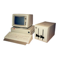
IBM 6580 Manuals
Manuals and User Guides for IBM 6580. We have
3
IBM 6580 manuals available for free PDF download: Product Support Manual
IBM 6580 Product Support Manual (263 pages)
Displaywriter System, Diskette Unit, Display Station
Brand:
IBM
| Category:
Monitor
| Size: 10.58 MB
Table of Contents
Table of Contents
5
Chapter 1. Introduction
11
Display Station
11
Work Station
12
Work Station Data Flow
12
Diskette Unit ~-2
12
Diskettes
12
Printers
13
Optional Paper Feed Assemblies
13
1-6. Mag Card Unit
14
Chapter 2. Operating Instructions
15
Display Formats
16
Status Lines
16
Scale Line
16
Typing and Menu Area
16
Prompt Line
16
Message Line
16
Keyboard Operation
18
Work Station Control Keys
19
Alphanumeric Keys
19
Function Control Keys
20
Cursor Movement Keys
21
Keyboard Arrangements
22
Menu Description
22
Menu Format
22
2-11. Margins and Tabs
24
Keyboard and Printer Description
24
Menu Sequence - Typing Tasks
25
Menu Sequence -Work Diskette Tasks
26
Menu Sequence - Program Diskette Tasks
27
Menu Sequence - Spelling Tasks
28
Menu Sequence - Change Format (CHG FMT) Key
29
2-17. Menu Sequence - Request (REQST) Key
30
Menu Sequence - Instructions
31
Chapter 3. 25-Line Display
33
25-Line Display Operational Theory
33
Character Structure
34
25-Line Display Fonts
37
Operating Voltages
38
Input Signals
39
25-Line Display Service Aids
39
25-Line Display Removal/Replacement
40
Chapter 4. Large Display
41
Locator
41
Large Display Operational Theory
42
Cabling
43
Data Flow
44
Character Structure
45
Operating Voltages
45
Internal Distribution Cable
47
Input Signals
48
Large Display Service Information
49
CRT Anode Discharge Procedure
50
Service Aids
51
Display Indicators
52
Large Display Adjustments
53
Image Size Adjustment
53
Image Centering Adjustment
54
Large Display Removals/Replacements
55
Large Display Module Removal
55
Rear Cover Removal
56
Display Analog Card Removal
57
High Voltage Power Supply Removal
59
4-23. Mainframe Assembly and Front Cover Removal
61
Chapter 5. Keyboard
63
Locator
63
Keyboard Operational Theory
64
Type a Key Modules
66
Keyboard Electronics
67
Basic Assurance Test (BAT)
70
Character Buffer
70
Keyboard Identification (ID)
70
Key Position
71
Code Key
72
Enter Key
72
Keyboard Speakers
72
Keyboard Arrangement Option
73
ASCII Code Set
75
Keyboard Logic Card
76
Keyboard Service Aids
77
Tools and Equipment
77
Cleaning Procedures
77
Adjustments
78
Shift Lock Brake Adjustment (Type a Only)
78
Removals/Replacements
79
Keyboard Cover (Type a & B)
79
Pad Card (Type a Only)
80
Key Module (Type a Only)
81
Fly Plate Replacement (Type a Only)
82
Shift-Lock Mechanism (Type a Only)
83
Spacebar Mechanism (Type a Only)
83
Chapter 6. System Electronics/Power Supply
85
Locator
85
System Electronics/Power Supply Theory
86
System Card
87
System Bus
87
Microprocessor
88
Read Only Storage (ROS)
89
Keyboard Adapter
90
Direct Memory Access (DMA)
90
Timer
90
Printer Data Link
90
Memory Cards
90
Program Memory Requirements
91
Diskette Adapter Card
91
Display Adapter Card
92
Printer Sharing Card
93
Power Supply Theory
95
Power on Reset
98
Removal Procedures
99
Cover Removal
99
Electronic Card(S) Removal
100
Distribution Board Removal
101
Power Supply Removal
102
Chapter 7. Diskette Unit
103
Locator
103
Diskette Unit Theory
104
Diskette Theory
105
Diskette Handling
106
Motor and Drive
108
Hub Drive and Collet
110
7-8. Led/Ptx
111
Head Load
112
Read/Write Head
113
Stepper Motor - Head Carriage Assembly
114
Diskette Adapter Card
116
File Control Card
117
Power/Signal Distribution
121
Error Sensing
122
Dual Drive
124
Service Aid
125
Special Tools
125
Adjustments
126
Operator Handle Adjustment, Collet/Flat Spring Adjustment Check
126
Solenoid and Bail Adjustment
128
Stepper Drive Band Adjustment
130
Head Carriage Adjustment
132
Removals/Replacements
134
Cover Removal
134
Head Load Bail Removal
134
Collet/Flat Spring Removal
135
Right Diskette Drive Removal
136
Diskette Guide Assembly Removal
137
Head Load Arm Pad Removal/Replacement
138
Bail Solenoid and Idler Removal
139
LED and Ptx/File Control Card Removal
140
Diskette Adapter Card Removal
141
Head/Carriage Assembly Removal (Type 1 and Type 2D Drive)
142
Pulley and Drive Band Removal
142
Drive Band Replacement
143
Stepper Motor Removal 7·41
143
AC Drive Motor Capacitor Removal 7~42
144
AC Drive Motor Removal
146
AC Drive Motor Replacement
146
Chapter 8. Cables/Connectors/Test Points
149
Power Supply
155
Electronics Module
158
Light Emitting Diode (LED) Board
166
Printer
167
Mag Card Unit
168
Communications Connectors
168
25-Line Display Module
169
Large Display
170
Diskette Unit
176
Printer Sharing
188
Type a Keyboard Module
189
Type B Keyboard Module
190
Chapter 9. Diagnostics
193
Diagnostics Theory
193
Resident Diagnostics Description
193
Power on Reset (POR)
194
Basic Assurance Test (BAT)
194
BAT before Display Initialization
196
BAT after Display Initialization
197
9-6. BAT Progress/Error Codes
198
Resident Non-Automatic (RNA) Diagnostics
199
RNA Diagnostic Tests and Functions
202
Loadable Diagnostics
205
Loadable Diagnostics Display Format
210
Loadable Diagnostics Keyboard Functions
212
Map Diagnostic Integration (MDI)
213
MDI Entry
213
MDI Function
213
MDI Device Selection Menu
214
MDI Run Time Options
214
MDI Test Unit Menu Numbering
215
MDI Run Time Options Menu - Stop on Options
215
Trace Display
215
MDI Display Typing Area or Menu Area
216
MDI Prompt Responses
216
MDI Prompts
217
Loadable Utilities
220
Error Log Utility Group
221
System Error Log
222
Error Log Dump Procedure
224
Diskette Unit (6360) Head Alignment Compatibility Check
224
Field Engineering Service Number/Release Version Modification (FESN/RVM)
225
System Exerciser
225
Load Program Function
226
Maintenance Analysis Procedures (Maps)
227
MAP Format
227
Problem Determination Procedures (PDP)
230
Chapter 10. Introduction
231
Data Collection
231
Instructions
231
Problem Isolation
232
Keyboard Isolation
234
Display Isolation
235
Electronic Module Isolation
236
5218 Printer Isolation
240
Printer Sharing Isolation
241
Questions
246
Recommendation
247
History Build
248
BAT Failures
251
Pre-CRT Initialization BAT Failures
251
Post-CRT Initialization BAT Failures
251
Drive Set Ready Test (L)
252
Stepper Motor Phase Test (M)
252
Track Step Test (T)
252
Trace Table Usage
255
Intermittent Problem Diagnostic Approach
255
Advertisement
IBM 6580 Product Support Manual (133 pages)
Displaywritter system
Brand:
IBM
| Category:
Desktop
| Size: 8.62 MB
Table of Contents
Table of Contents
5
Service Information Service Aid
5
Operator Controls
7
Fonts
8
Display
9
Keyboard
11
Locator
12
Basic Assurance Test (BAT)
13
Matrix Chart
14
Dataflow
15
Keybutton Position
16
Tools and Equipment
17
Keyboard Arrangements
17
Cleaning Procedures
17
Shift Lock Brake Adjustment
18
Keyboard Cover
19
Pad Card
19
Key Module
20
Fly Plate Replacement
21
Shift-Lock Mechanism
22
Spacebar Mechanism
22
Key Module Operation
13
Shift-Lock Mechanism
13
System Electronics Power Supply
23
Service Information Locator
24
DC Voltage Distribution
25
Leds
25
Lh1Js
25
AC Voltages
26
Currents
26
DC Voltages
26
Fuses
26
Printer Sharing Configuration
26
Cover
27
Electronic Cards
27
Removals/Replacements Cover
27
Distribution Board
28
Power Supply
29
Service Information Locator/Removals/Replacements Cover
31
Diskette Unit
32
Service Information Locator
32
Service Aid
32
Diskette Handling
33
Data Flow
34
Power/Signal Distribution
35
Read/Write Flowchart
36
Service Aid
37
Special Tools
37
Operator Handle Adjustment, Collet/Flat Spring Adjustment Check
38
Operator Handle Adjustment. Collet/Flat Spring
38
Adjustment Check
38
Solenoid and Bail Adjustment
39
Stepper Drive Band Adjustment
41
Head Carriage Adjustment
42
Cover
43
Right Diskette Drive
43
Head Load Bail
43
Removals/Replacements Cover
43
Diskette Guide Assembly
44
Diskette Guide Assembly Removal
44
Head Load Arm Pad Replacement
45
Bail Solenoid and Idler
46
LED and Ptx/File Control Card
47
Diskette Adapter Card
48
Head/Carriage Assembly
48
Pulley and Drive Band
49
Stepper Motor
49
Drive Band Replacement
49
Cables, Connectors & Test Points
51
Locator Chart (for Use with Maps)
52
AC Voltage Wiring Diagram
59
AC Voltage Grounding Path Schematic
62
Locator Chart (Point to Point Wiring Checks)
66
Table of Contents
93
Basic Assurance Test (BA T)
94
Basic Assurance Test (BAT)
94
Bat Progress/Error Codes
95
Display Format
95
Resident Non-Automatic (Rna) Diagnostics
96
Display Format
97
Diagnostic Tests
98
Customer Engineer (CE) Loadable Diagnostics
99
Display Format
100
Keyboard Function
101
MDT Run Time Options
101
MDT Run Time Options Menu· Stop on Options
101
MDI Test Unit Numbering
101
Keyboard Functions
101
MDI Run Time Options
101
MDI Run Time Options Menu - Stop on Options
101
MDI Prompt Responses
102
MDI Prompts
103
MDI Display Typing Area or Menu Area
105
MDI Trace Display
106
CE Utilities
107
Utili~Y Group
107
System Error Log
107
Error Log Utility Group
107
Error Log Dump Procedure
108
System Exerciser
109
Diskette Unit (6360) Head Alignment Compatabiliry Check
110
Field Engineering Service Number/Release Version Modification (FESN/RVM)
110
Licensed Program Guidelines
110
Load Program Function
110
Memory Card Configuration
110
Diskette Unit (6360) Head Alignment Compatibility Check
110
Modification (FESN/RVM)
110
Table of Contents
111
Intermittent Problem Diagnostic Approach
112
Introduction
112
Data Coliection
113
Instructions
113
Problem Isolation
113
Data Collection
113
Section 1 Keyboard Isolation
114
Section 2 Display Isolation
115
Section 2- Display Isolation
115
Section 3 Electronic Module Isolation
115
Section 4 Diskette Unitlsolation
116
Section 4 Diskette Unit Isolation
116
Section 5 5215 Printer Isolation
117
Section 6 5218 Printer Isolation
118
Section 7 Printer Sharing Isolation
118
Section 8 Power Supply Isolation
119
Section 9 Isolation Undetermined
119
Section 10 Software/Operator Procedures
120
Section 11 Environment
120
Questions
120
Recommendation
120
Section 12 History Build
121
Section 13 Service Request Numbers
121
Section 14 BAT Failures
122
Pre-CRT Initialization BAT Failures
122
Pre·cr T Initialization BAT Failures
122
Post-CRT Initialization BAT Failures
122
Section 15 Diskette RNA Test Failure Codes
122
Drive Set Ready Test (L)
122
Stepper Motor Phase Test (M)
122
P",St·crt Initialization BAT Failures
122
Track Step Test (T)
123
Section 16 Guidelines for Error Log Interpretation
123
Section 17 Trace Table Usage
124
Menu Sequences
125
Typing Tasks
126
Work Diskette Tasks
127
Program Diskette Tasks
128
Spelling Tasks
129
Operating Instructions
125
Change Format Key
130
Request Key
131
Instructions
132
IBM 6580 Product Support Manual (163 pages)
Displaywriter system
Brand:
IBM
| Category:
Desktop
| Size: 6.92 MB
Table of Contents
Table of Contents
3
25-Llne DISPLAY
7
Service Aid
7
Removals/Replacements
11
Safety
11
Safety Instructions
11
Service Aids, Operator Control
11
Adjustments
11
Rear Cover
14
Low Voltage Power Supply
14
High Voltage Power Supply
14
Mainframe Assembly and
27
Keyboard/Service Information Locator
29
Keyboard
29
Keybutton Position
29
Service Information Locator
29
Shift-Lock Mechanism
29
Basic Assurance Test (BAT)
29
Matrix Chart
29
Tools and Equipment
29
Locator
30
Key Module Operation
31
Shift-Lock Mechanism
31
Basic Assurance Test (BAT)
31
Matrix Chart
32
Dataflow
33
Keybutton Position
34
Cleaning Procedures
35
Keyboard Arrangements
35
Tools and Equipment
35
Adjustments
36
Shift Lock Brake Adjustment
36
Keyboard Cover
37
Pad Card
37
Key Module
38
Fly Plate Replacement
39
Shift-Lock Mechanism
40
Spacebar Mechanism
40
System Electronics Power Supply
41
Service Information Locator
42
Leds
43
DC Voltage Distribution
43
System Grounding Path Schematic
44
Fuses
45
A C Voltages
45
DC Voltages
45
Currents
45
Printer Sharing Configuration
45
Cover
46
Removals/Replacements
46
Electronic Cards
46
Distribution Board
47
Power Supply
48
Service Aid/Power/Signal Distribution
49
Power/Signal Distribution
49
Read/Write Flowchart
49
Special Tools
49
Solenoid and Bail Adjustment
49
Stepper Drive Band Adjustment
49
Removals/Replacements
49
Right Diskette Drive
49
Head Load Bail
49
Diskette Guide Assembly
50
Service Information Locator
50
Service Aid
50
Diskette Handling
51
Data Flow
52
Power/Signal Distribution
53
Read/Write Flowchart
54
Service Aid
55
Special Tools
55
Collet/Flat Spring
56
Operator Handle Adjustment, Collet/Flat Spring Adjustment Check
56
Solenoid and Bail Adjustment
57
Stepper Drive Band Adjustment
59
Head Carriage Adjustment
60
Service Aid
49
Removals / Replacements Cover
61
Right Diskette Drive
61
Head Load Bail
61
Diskette Guide Assembly Removal
62
Collet/Flat Spring Removal
63
Head Load Arm Pad Replacement
64
Bail Solenoid and Idler
65
LED and PTX/ File Control Card
66
Diskette Adapter Card
67
Head/Carriage Assembly
67
Pulley and Drive Band
68
Stepper Motor
68
Drive Band Replacement
68
AC Drive Motor
70
Acdrivemotor
70
Capacitor
72
Cables, Connectors & Test Points
73
Locator Chart (for Use with Maps)
73
Locator Chart (Point to Point Wiring Checks)
73
Advertisement
Advertisement
Related Products
IBM NetVista 6578
IBM 6565 - PC 300 PL
IBM 6587 - PC 350 - 16 MB RAM
IBM NetVista 6579
IBM NetVista 6568
IBM NetVista 6569
IBM 6589 - PC 365 - 32 MB RAM
IBM 6589
IBM 6278
IBM NetVista 6286
IBM Categories
Server
Desktop
Storage
Laptop
Monitor
More IBM Manuals
Login
Sign In
OR
Sign in with Facebook
Sign in with Google
Upload manual
Upload from disk
Upload from URL