Sign In
Upload
Manuals
Brands
IBM Manuals
Computer Hardware
2025
IBM 2025 Manuals
Manuals and User Guides for IBM 2025. We have
1
IBM 2025 manual available for free PDF download: Maintenance Manual
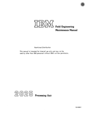
IBM 2025 Maintenance Manual (275 pages)
Processing Unit
Brand:
IBM
| Category:
Computer Hardware
| Size: 24.64 MB
Table of Contents
Preface
2
Table of Contents
3
Abbreviations
7
Safety
10
Chapter 1. Reference Data and Diagnostic Techniques
11
Section 1. Reference Data
11
Core Storage (Figures 1-1 through 1-17)
11
Trap Addresses
12
Address Stop/Match
12
Auxiliary Storage Maps (Figures 1-7 through 1-17)
16
2540 Reader/Punch (Figures 1-18 through 1-23)
25
1400 Compatitiility Feature (Figures 1-27 through 1-33)
30
Auxiliary Storage Module 0 (1400 Compatibility)
32
Auxiliary Storage Module 1 (1400 Compatibility)
34
Auxiliary Storage Module 2 (1400 Compatibility)
34
Auxiliary Storage Module 3 (1400 Compatibility)
35
Auxiliary Storage Module 4 (1400 Compatibility)
35
Auxiliary Storage Module 5 (1400 Compatibility)
35
Auxiliary Storage Module
35
Systems--1400 Compatibility)
35
Local Storage (1400 Compatibility)
35
Zone 0 (1400 Compatibility)
35
Zone 6 (1400 Compatibility)
36
Zone 7 (1400 Compatibility)
36
PR-KB (Printer-Keyboard) Figures 1-34 through
40
(Figure 1-4 7)
43
Cpu.mode
46
2311 Disk Mode
53
1403 Mode
53
2540 Reader Mode
54
(EXT to CPU)
56
(CPU to EXT)
61
(EXT to CPU)
70
(CPU to EXT)
71
Ext to Cpu
76
Local-Storage Location Decode
77
Program Codes and PSW (Figures 1-60 through 1-63)
85
Channel Command and Address Formats (Figures 1-64 through 1-68)
87
1403 Printer (Figures 1-73 through 1-95)
95
2311/DAC (Figures 1-96 through 1-118)
114
Section 2. Diagnostic Techniques
122
Maintenance Concepts
122
Malfunction Indications
122
Unit Identification
123
Malfunction Isolation
123
Repair
123
Repair Verification
123
Protection of Control Storage, CSL
124
Error Handling
124
Interface Control Check
126
1052Logout
126
CPU Hardware Checks
126
CPU Microprogram Checks
126
CPU Attachment Checks
127
2540 Attachment Checks
127
2311 Attaclunent Checks
127
Channel Checks
127
System Checks
128
Low Temperature
128
External Branch Conditions
128
Integrated 1403 Attachment
129
System Control Panel
130
CPU Status Indicators
132
Alter/Display PR-KB
132
Csl
132
Allow Manual
133
Clock off
133
System Checks
133
Low Temperature
133
Power Check
133
PCH (Punch)
133
RDR (Reader)
133
CHNL (Channel)
133
File
133
CPU Checks
133
Operator's Control Panel (OCP) Indicators
134
Power on Key
134
Pluggable Indicators
134
Control Storage Load
134
PSW Restart
134
Control Address Set
134
Enable Control Storage Store
134
Printer-Keyboard Alter/Display
134
Diagnostic Control Switch
134
Stop
134
Single Address as
135
Load Program Storage
135
Load Storage
135
Engineering Changes (Ec's)
136
Field Microprogram Changes
136
Field Change Exceptions
136
Unique Considerations
136
Multisystem Configuration
136
1401/1460 and 1440 Compatibility Features
136
Machine-Check Trap and 1052 Logout
136
Diagnose Instruction
137
CE Trap
137
CE Test Panel Hubs
137
Programming Errors
137
Local Storage Zone and External Mode
137
For 2560
137
Stop Position
138
Trap Position
138
Power and Cooling
138
Failure Detection, Indication, and Isolation
138
Cooling Facilities
139
Warm-Up
139
Convenience Outlets
139
Main Storage Diagnostic Aids
139
Andy Decode Numbering Scheme
139
Scoping Storage
140
Resistors
140
Resistors
142
Array Sense Line Checking
142
Chapter 2. Console and Maintenance Features
150
Section 1. Basic Unit
150
Storage Protect Key--Display
150
Patch Card Generation
150
Debe-2
150
1401 Emulator CSL Deck
151
1403 Buffer Load Microloop
152
Soft-Stop Loop--Single Cycling
152
Worst-Case Storage Scan Definition
152
MS Address Stop Procedure During IPL or CSL
152
Psw
153
PSW Restart
153
Procedure
153
Display of Current PSW
153
Description
153
Reader Checks During CSL
154
Checksum Routine--BCHK
154
Initializing Procedure--Checksum
154
System Configuration--CSL
155
BCPL Routine
156
Restrictions When Punching CSL Cards
156
Card
156
Metering Switch (CE Switch)
157
Display Operations
157
Program Storage Display
157
Auxiliary-Storage Display
157
Program-Storage Store
158
Auxiliary-Storage Store
158
SECTION La. PR-KB PROCEDURES
159
Addressing, Console Printer-Keyboard
159
Program-Controlled Operations
159
Channel Commands
159
Setup
159
Addressing
159
Execution of Alter or Display
160
End Operation
160
Message Formats
160
Alter Storage
160
Display Storage
161
Logout
161
Suggested Restart Procedures for Integrated PR-KB
162
Sense Bits 4, 5, 6, and
163
TI (1052 Data In)
163
TR (1052 Tilt/Rotate Register)
163
TD (1052 Diagnostic Branch Conditions)
163
TT (1052 Branch Conditions)
163
TU (1052 Diagnostic Branch Conditions)
163
CPU to External Facilities (1052)
164
TE (1052 Data Out)
164
SECTION Lb. 1403 PROCEDURES
165
Checks (1403)
165
PLB Parity Check
165
Hammer Check
166
Hammer Driver Coil--Fuses
166
Sync Check
166
Additional Checks
167
Forms Check
167
End of Forms
167
Suggested Restart Procedures for 1403
167
Command Reject (Sense Bit 0)
167
Intervention Required (Sense Bit 1)
167
Bus-Out Check (Sense Bit 2)
168
Data Check (Sense Bit 4)--MCS Only
168
Sense Bit
169
Resets (Integrated 1403)
169
2:36 External to CPU Facilities (1403)
169
PRI (Print Line Buffer Data-In)
169
PRS (1403 Sense/Status Conditions)
169
PRD (Diagnostic Conditions)
170
Diagnostic Decode
170
CPU to External Facilities (1403)
170
PRC (Carriage Control Register Data-Out)
170
MCS Table--Utility Program
171
SECTION Lc. 2311/DAC Procedures
172
Addressing--2311 Disk Storage Drive
172
Sense Conditions, DAC
173
Track Orientation
173
Error Recovery Procedures, 2311 DAC
175
Error Conditions Table, 2311 DAC
175
SECTION Ld. 2540 PROCEDURES
178
Addressing, Integrated 2540 Attachment
178
2540 Restarts from Error Conditions
178
Jam Removal
182
External to CPU Facilities
182
Rpl (Reader-Punch Data In)
182
RS (Reader Branch Conditions)
182
PS (Punch Branch Conditions)
183
RPS (Reader and Punch Branch Conditions)
183
Rpdl
183
RPD2 (Diagnostic Reader/Punch Branch Conditions)
183
RP= K (CS Decode= D)
185
D K (Cs Decode 9)
185
SECTION Le. CHANNEL PROCEDURES
186
Multiplexer Channel Device Addressing
186
Channel and Unit Addressing Restrictions
186
Channel
189
The MPX Channel and ICA Features)
189
Assigning Integrated 1052, 1403, 2311, and 2540 Device Addresses
189
Channel Status (Byte 0)
190
Op-Flag (Byte 1)
190
Data Address (Bytes 2 and 3)
190
Count (Bytes 4 and 5)
191
Next CCW Address (Byte 6 and 7)
191
Channel Status (LS Zone 7 Register GO)
191
Data Addrt!Ss (LS Zone 7 Register V)
191
Count (LS Zone 7 Register U)
191
Next CCW Address (Auxiliary Storage Location 008A)
191
Channel Error-Handling Philosophy and Logout
191
Channel Status Byte
192
Logout
192
Channel Control Check Logout
192
Interface Control Check Logout
193
Standard Interface Hardware
195
GS (Channel Branch Conditions)
195
GT (Channel Branch Conditions)
195
GD (Channel Diagnostic Register)
195
IN (Channel Bus-In)
196
CPU to External Facilities (Channel)
196
OUT (Channel Bus-Out)
196
SECTION Lf. ICA PROCEDURES
197
Nonoperational Lines
197
Station Selection Feature
197
Jumper Options
197
Section 2. Features
198
Multiple Character Set
198
2560 Procedures
198
Chapter 3. Preventive Maintenance
200
Section 1. Basic Unit
200
Section 2. Features
201
Chapter 4. Checks, Adjustments, and Removals
202
Section 1. Basic Unit
202
CPU Timing
202
Specifications
202
Core Storage Array Temperature Control
202
Cooling
202
Specification
202
Heating
202
Heater Adjustment
202
Schmoo Curve (Main Storage)
204
Example of Schmoo Curve Procedure
204
When to Schmoo
205
Service Checks
205
Worst-Case Patterns
205
Worst-Case Test
205
Four-Point Strobe Schmoo Procedure
205
Checkout Procedures
206
Scoping Main Storage
206
Two-Point Schmoo Procedure
206
Main Storage Replacement
206
Removing the 0-32K Unit
206
Removing the 32-64K Unit
207
Array Changing
207
Changing Diodes
207
Local Storage
207
Scoping Local Storage
207
Initial Delay Line Settings
207
Delay Lines (Local Storage) Adjustment
207
Local Storage/Storage Protect Cards
208
SCR Circuits
208
Replacement
209
System Reset, IPL, or CSL--Singleshot
209
Adjustment
209
Operational Out--Singleshot
209
Checkout Procedure
209
2540 Attachment
209
Advertisement
Advertisement
Related Products
IBM Redbooks 2/4 Port Ethernet Expansion Card
IBM 2740-1
IBM 2740-2
IBM 200/400
IBM 29
IBM 2740
IBM 2741
IBM 2780
IBM 202
IBM 2027-R16
IBM Categories
Server
Desktop
Storage
Laptop
Monitor
More IBM Manuals
Login
Sign In
OR
Sign in with Facebook
Sign in with Google
Upload manual
Upload from disk
Upload from URL