Sign In
Upload
Manuals
Brands
Honeywell Manuals
Transmitter
SmartLine SLN 700 87B
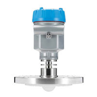
Honeywell SmartLine SLN 700 87B Manuals
Manuals and User Guides for Honeywell SmartLine SLN 700 87B. We have
1
Honeywell SmartLine SLN 700 87B manual available for free PDF download: User Manual
Honeywell SmartLine SLN 700 87B User Manual (54 pages)
Level Transmitter, Non-Contact Radar
Brand:
Honeywell
| Category:
Transmitter
| Size: 1.23 MB
Table of Contents
Table of Contents
7
1 Introduction
9
Overview
9
Transmitter Models
9
Transmitter Components
9
Overview of Components
9
Figure 1-1 Components of the Level Transmitter
9
Electronics
10
Process Connector
10
Table 1-1: Process Connector
10
Communicating with the Transmitter
11
SLN 700 Transmitter Label
11
Figure 1-2: SLN 700 Transmitter Label Example
11
Transmitter Model Number Description
12
Safety Certification Information
12
Figure 1-3: Standard SLN 700 Model Number
12
2 Radar Level Measurement
13
Overview
13
Theory of Operation
13
3 Mounting
14
Figure 3-1: Graphical Illustration
14
Moisture-Proof
15
Figure 3-2: Moisture-Proof Diagram
15
Installation Position
16
Figure 3-3: Installation Position, >200 MM
16
Table 3-1: Minimal Distance to Tank Wall
16
Figure 3-4: Conical Vessel Installation
17
Nozzle Installations
18
Figure 3-5: Nozzle Specifications Diagram
18
Table 3-2: Nozzle Specifications Table
18
Correct and Incorrect Installation Position
19
Figure 3-6: Correct and Incorrect Installation Position
19
Figure 3-7: Correct and Incorrect Installation Position
19
Installations with Agitation
20
Figure 3-8: Installation of Reflecting Plate
20
Figure 3-9: Agitation
20
4 Transmitter Installation
21
Supply Voltage
21
Figure 4-1: Maximum Loop Resistance (Ω)
21
Table 4-1: Maximum Loop Resistance (Ω)
21
Installation of Connecting Cables
22
General Introduction
22
Wiring Mode
22
2-Wire
22
Figure 4-2: 2-Wire Wiring for HART
22
Hazardous Location - Intrinsic Safety
23
Table 4-2: Hazardous Location Ratings
23
Table 4-3: Intrinsic Safety Entity Parameters
23
Table 4-4: Process Temperature Vs Temperature Class
23
Figure 4-3: Intrinsically Safe Wiring
24
5 Operating the Transmitter
25
Functions of Keys
25
Figure 5-1: Instrument Panel 4-Key
25
Table 5-1: Keys of LCD
25
Table 5-2: Display Menu Tree Basic Settings, Display and Diagnostics
40
Table 5-3: Display Menu Tree Advanced Settings and System
42
Figure 5-2: Representation of an Echo Curve Defining the Echo Threshold and the Envelope Offset
43
6 Maintenance
44
Configuration Method
44
Configuration with Display
44
Configuration
45
Figure 6-1: Connect Via HART Hand-Held
45
Procedures
46
Output Check Procedures
46
Constant Current Source Mode Procedure (Loop Test)
46
Error Codes
47
Glossary
48
Advertisement
Advertisement
Related Products
Honeywell SmartLine SLN 700 87A
Honeywell SmartLine SLN 700 87C
Honeywell SmartLine SLN 700 87D
Honeywell SmartLine SLN 700 83A
Honeywell SmartLine SLN 700 82A
Honeywell SmartLine SLN 700 83B
Honeywell SmartLine SLN 700 83C
Honeywell SmartLine SLN 700 82C
Honeywell SmartLine SLN 700 82D
Honeywell SmartLine SLN 700 83D
Honeywell Categories
Thermostat
Controller
Control Unit
Security Camera
Accessories
More Honeywell Manuals
Login
Sign In
OR
Sign in with Facebook
Sign in with Google
Upload manual
Upload from disk
Upload from URL