Sign In
Upload
Manuals
Brands
Honeywell Manuals
Measuring Instruments
enCore Series
Honeywell enCore Series Manuals
Manuals and User Guides for Honeywell enCore Series. We have
2
Honeywell enCore Series manuals available for free PDF download: Manual, Operating Instructions Manual
Honeywell enCore Series Manual (315 pages)
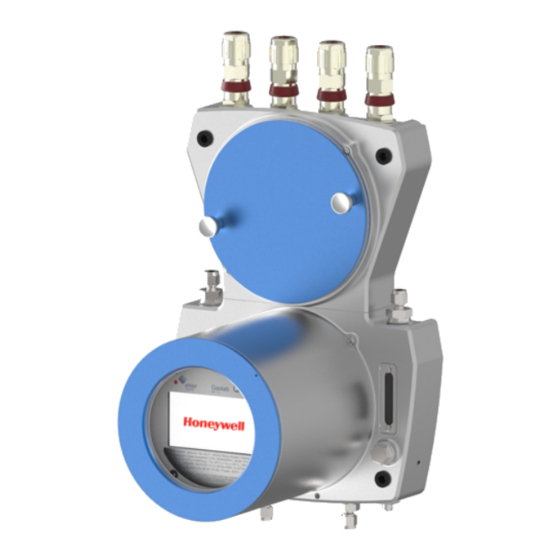
Gas Quality Analyzer
Brand:
Honeywell
| Category:
Measuring Instruments
| Size: 14.34 MB
Table of Contents
Table of Contents
3
About this Document
8
Aim / Scope
8
Important Notes to this Document
9
Abbreviations
12
Safety Information (EN-US-FRA)
16
Intended Use
18
Specific Condition of Use
20
Place of Use Environmental Conditions and Installation
21
Required Knowledge of the Personnel
23
Information and Warnings on the Device
25
Safety Information about Gases and Pressures
27
Handling Explosion-Protection Devices
29
Electrical Safety Information
33
Disconnecting Device and Cables
35
Conduit Systems and Cable Glands
37
Data Safety Information
39
Security Considerations for Your Network
39
Enforce a Strong Password Policy
39
Preventing Unauthorized External Access
40
Security for Data at Rest and Data in Transit
42
Structure and Inscriptions of Gaslab Q2
44
Connection Section
45
Instrumentation Section
47
Human-Machine Interface (HMI)
49
Type Labels and Setting Marks
50
Measuring Method and Measuring Point
55
Description of the Measuring Method
55
Measuring Point Overview
57
Gaslab Q2 after Delivery and at the Place of Use
58
Storing Gaslab Q2
59
Transporting Gaslab Q2
60
Mechanical Installation Gaslab Q2
61
Place of Use and Installation
62
Device Dimensions
64
Fluidic Installation of the Measuring Device
65
Fluid Interfaces
66
Connect the Vent Gas Line
67
Connect the Process Gas Line
69
Connect/Replace Calibration-, Verification- Gas Cylinders
70
Opening and Closing Gaslab Q2
70
Opening Gaslab Q2
70
Closing the Housing of Gaslab Q2
72
Securing the Detachable Parts for Opening the Housing
73
Electrical Installation
74
Power Supply and Electric Protection
75
Cables (Power Supply / Communication)
76
Grounding and Potential Equalisation
77
Cable Glands (Adapter / Dummy Plugs)
78
Electrical Connection Diagram and Electrical Interfaces (Inputs and Outputs)
81
Connection to Other Devices and System Parts
83
Electrical Device Test to Verify Correct Installation
91
Commissioning and Decommissioning
92
Commissioning Preparations and Requirements
93
Set Date and Time
93
Set Password for Administrator (Admin1) and Generate a New TLS Certificate
94
Adapting the Factory Parameterization
95
The Hardware Parameter Guard (SSW)
96
Additional Conditions for Fiscal Metering
98
Standard Commissioning and Normal Operation
99
Checking the Setting and Signals
100
Decommissioning and Disposal
101
Decommissioning and Disassembly
101
Disposal
103
Gaslab Q2 Operation Panel and Operation
104
Leds on the Operation Panel
105
Screen Display on the Operation Panel
106
Superimposition Keys
107
Different Types of Device Displays
108
Navigation Options
109
The Middle of the Bottom Status Line
110
Visibility of the Displays
111
Entries and Changes Using the Operation Panel
112
Displays and Functions
115
Home Display (Overview)
115
Info Display (Overview)
118
Error List - Main Display (Accept / Quit Error Messages)
125
System Display (Overview)
127
System Display Time Service (System Time and Date)
128
System Display Users (Login, Logout, Password)
134
System Display (Logbook)
140
System Display (Audit Trail)
141
System Display I/O (Network Settings / Inputs/ Outputs)
144
Display Q2 Sensor Values
146
Display Q2 Control (Calibration/Verification/Touch)
147
Q2 Main Display (Calculation Standard)
149
Display User Archives
155
Display Modbus
157
Operation and Operating Modes of Gaslab Q2
164
Operating Mode: Analysis (Automatic Normal Operation)
164
Operating Mode: Operational Calibration (Manual)
165
Operating Mode: Verification (Special Mode)
167
Configuration and Analysis Software Ensuite
171
Ensuite Basis of Use
172
First Steps to Use Ensuite
172
Data Connection to the Measuring Device
176
Saving and Managing the Device Setting
182
Update Downgrade and Bugfix-Software
188
Changing Basic (System) Settings
190
SFB I/O (IP Address Network- and I/O-Settings)
190
System Settings
193
Time Service SFB Settings and System Time Action
194
Settings Unit Service SFB and Displays
196
User and Rights Management
201
Fiscal Parameters and Optional Using of Approval File
219
Live Data and Trending Actions in Ensuite
221
Notices about Parameterization
229
Offline Parameterization
230
Online Parameterization
233
Editing Parameterizations
234
Change Settings of the Q2 AFB
236
Setting or Changing Automatic Measurements
236
Using Ensuite Functions and Other Afbs
239
Working with Archives and Logs
239
Displaying and Reading Analysis Results
243
Working with the Modbus AFB
243
The Remote Operation Panel Actions
244
Activate / Deactivate Remote Operation Panel
244
Enabling the Local Device Functions
245
Possible Malfunctions and Troubleshooting
247
Possible Error Events
247
Disturbances During Normal Operation (Troubleshooting)
248
Correct the Gas Supply Failures
249
Pressure Alarm Analysis
250
Check Pressure Sensor (Function)
251
Correct Electrical Faults
253
Correct Communication Errors
256
Resolving a "Protocol Error" (Message)
257
Sensor Errors
258
Eliminate Start-Up Errors
259
Maintenance, Cleaning and Repair
260
Spare Parts and Repairs
260
Maintenance and Maintenance Intervals at a Glance
261
Inspection Work in Detail
263
Checking the Battery Charge
263
Info Display (Display Test)
264
Check the Tightness of the Installation
264
Check Cylinder Pressure (Visual Check)
266
Check Inlet Pressures (Visual Check)
267
Checking Flows (Optical Control)
268
Check Housing Parts (Visual Inspection)
269
Check Connections (Visual Check)
270
Check Breather(S) / Device Venting
271
Advertisement
Honeywell enCore Series Operating Instructions Manual (133 pages)
Flow Computer
Brand:
Honeywell
| Category:
Measuring Instruments
| Size: 6.11 MB
Table of Contents
Table of Contents
3
1 General Information
8
The Encore/Ensuite Concept
8
Scope of Delivery
9
2 About These Instructions
11
Target Group Definition
11
The Encore FC Manual at a Glance
13
Text Labelling
15
Presentation of Safety and Risk Instructions
15
Paragraph Formats
16
Character Formats
17
Character Formats in Flow Charts
18
Limitation of Liability
19
Applicable Standards and Guidelines
20
3 Security Considerations for Your Network
21
4 Safety
23
General Safety Instructions
23
Intended Use
25
Unacceptable Use While Impaired
26
Operator Liability
26
5 Design and Function
28
Functional Description of Encore FC Devices
28
Number of Streams and Their Flow Directions
29
International Standards
29
Device Description
30
Operation Panel
31
Device Keys
32
Touch Screen
32
Operation and Navigation Within the Display
33
Security Switch
36
Leds
36
Interfaces (Rear Side of Device)
39
Available Process Boards
40
Exmfe5 Process Board
40
MFE7 Process Board
43
MSER4 Process Board
43
ESER4 Process Board
44
MFA8 Process Board
44
6 Assembly Instructions
45
Line Connection
45
Power Supply and Grounding
47
Installation and Conversion of Process Boards
48
Insert a Process Board in a Free Board Slot
49
Connection Diagrams
54
General Recommendations for Signal and Data Cable
55
Pt100 (Eex I) Via Exmfe5 Board
57
Pt100 (Eex D) Via MFE7 Board
58
Analog Measurement Transmitter (Eex I) Via Exmfe5 Board
59
Analog Measurement Transmitter (Eex D) Via MFE7 Board (Without Barrier)
60
Analog Measurement Transmitter (Eex I) Via MFE7 Board (Barrier in Sink Mode)
61
Analog Measurement Transmitter (Eex I) Via MFE7 Board (Barrier in Source Mode)
62
HART Measurement Transmitter (Eex I) Via Exmfe5 Board
63
HART Measurement Transmitter (Eex D) Via MFE7 Board (Without Barrier, Internal Power Supply)
65
HART Measurement Transmitter (Eex D) Via MFE7 Board (Without Barrier, External Power Supply)
67
HART Measurement Transmitter (Eex I) Via MFE7 Board (Barrier in Sink Mode)
69
HART Measurement Transmitter (Eex I) Via MFE7 Board (Barrier in Source Mode)
71
HART Measurement Transmitter (Eex D) Via MFE7 Board (Redundant, Without Barrier) - Burst Mode
73
HART Measurement Transmitter (Eex I) Via MFE7 Board (Redundant, Barrier in Source Mode) - Burst Mode
75
HART Measurement Transmitter (Eex D) Via MFE7 Board (Multi-Master, Without Barrier) - Multidrop Mode (from Basic System 03-25)
77
HART Measurement Transmitter (Eex I) Via MFE7 Board (Multi-Master, Barrier in Source Mode) - Multidrop Mode (from Basic System 03-25)
79
Gas Meter (Turbine): Encoder Index, 2 LF/HF Sensors (Eex I)
81
Gas Meter (Turbine): Encoder Index, 2 LF/HF Sensors (Eex I) Via Exmfe5 Boards
81
Gas Meter (Turbine): Encoder Index, 2 LF/HF Sensors (Eex I) Via MFE7 Board
82
Gas Meter (Turbine) SMRI Bi-Directional: 2 HF Sensors, Flow Direction Detection (Eex I) Via MFE7 Board
84
Gas Meter (Turbine) SMRI Bi-Directional: Flow Direction Detection Internal (Eex I) Via MFE7 Board
85
Q.sonic Ultrasound Gas Meter: Serial RS485 (Eex D) Via MFE7 Board
87
Q.sonic6 Ultrasound Gas Meter: Serial RS485 (Eex D) Via MFE7 Board
88
FLOWSIC600 Ultrasound Gas Meter: Serial RS485 (Eex D)
89
FLOWSIC600 Ultrasound Gas Meter: Serial RS485 (Eex D) Via MFE7 Board
89
Serial Interface through COM Port (CPU or MSER4-Board)
90
Analog Output over MFA8 Board (0/4
92
Message Output over MFA8 Board
93
Pulse Output over MFA8 Board
95
7 Device Configuration and Commissioning
96
Device Configuration
97
Commissioning the Measurement System
98
Checking Device Settings
99
Checking Measurement Input Values
99
Checking Output Signals
99
Checking Digital Communication (Modbus, Etc.)
99
Checking Measurements and Calculations
99
End of Commissioning (from Basic System 03-24)
99
Sealing (if Necessary)
100
8 Maintenance
101
Battery Replacement
101
Changing Batteries
102
Cleaning
104
Technical Assistance Center (TAC)
105
Replacement Parts and Accessories
105
Warranty Conditions
106
9 Decommissioning/Disposal
107
Storage
107
Disposal
108
10 Technical Data
109
General Information
109
Input Channels
110
Outputs
111
Interfaces for Digital Communication
112
Data Protocols
112
Data Protocols and Its TCP Default Port (Ethernet)
113
Housing Dimensions
114
1/3 Housing Width
114
1/2 Housing Width
115
11 Faqs
116
How to Report a Security Vulnerability to Honeywell
116
Limitations for Multidrop and Burst Mode up to Basic System Version
116
Index
118
Appendix
120
Advertisement
Related Products
Honeywell enCore FC Series
Honeywell Enraf 854 ATG
Honeywell Envitec MySignO
Honeywell ENCAL 3000
Honeywell Enraf 977
Honeywell EW450A2000
Honeywell EW452A5900
Honeywell EW449P7700
Honeywell EW452P7700
Honeywell E-Mon EM3S-V-P-J
Honeywell Categories
Thermostat
Controller
Control Unit
Security Camera
Accessories
More Honeywell Manuals
Login
Sign In
OR
Sign in with Facebook
Sign in with Google
Upload manual
Upload from disk
Upload from URL