Sign In
Upload
Manuals
Brands
GE Manuals
UPS
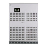
SG SERIES 40
GE SG SERIES 40 Manuals
Manuals and User Guides for GE SG SERIES 40. We have
2
GE SG SERIES 40 manuals available for free PDF download: Installation Manual, Operating Manual
GE SG SERIES 40 Installation Manual (635 pages)
Brand:
GE
| Category:
UPS
| Size: 63.44 MB
Table of Contents
Section 1
5
Table of Contents
5
Safety Rules
6
Layout
9
Layout Sg Series 10 & 20
9
Layout Sg Series 30 & 40
9
Installation
11
Transport
11
Dimensions and Weight
11
Delivery
12
Storage
12
Storage of the UPS
12
Storage of Battery
12
Place of Installation
13
UPS Location
13
Battery Location
15
Ventilation and Cooling
16
Unpacking
17
Electrical Wiring
19
Utility Input Connection
19
Input/Output over Current Protection and Wire Sizing
20
Battery over Current Protection and Wire Sizing
21
Wiring Connection
24
Power Connections
24
Power Connection with Common Input Utility of SG Series 10 & 20
27
Power Connection with Common Input Utility of SG Series 30 & 40
28
Power Connection Dual Input Utility of SG Series 10 & 20
29
Power Connection Dual Input Utility of SG Series 30 & 40
31
Battery Connection of SG Series 10 & 20
33
Battery Connection of SG Series 30 & 40
33
Set-Up for SG Series 10-20-30-40 When Functioning as Frequency Converter
35
Rpa Parallel System Connection
36
Power Wiring of Parallel Units
36
Parallel Control Bus Connection
37
Control Bus Cable Location
39
Customer Interface
41
Serial Port J3
42
Output Free Potential Contacts
42
Programmable Input Free Contacts
43
Gen Set Signaling (GEN ON)
43
AUX External Maintenance Bypass
43
Auxiliary Power Supply (APS) 24 VDC
43
EPO - Emergency Power Off" Command Connection
44
Notes
46
Notes Form
46
Section 2
51
Safety Rules
53
Layout
56
Layout Sg Series 10 & 20
56
Layout Sg Series 30 & 40
56
Introduction
58
Block Diagram and Main Elements
59
Description
59
Normal Operation Mode
60
Operation Modes
60
Utility Failure Operation
60
Automatic Bypass
61
Manual Bypass
61
Utility Recovery Operation
61
Introduction to the Parallel System
62
Parallel System Operation
62
Features of RPA Parallel System
63
Load Sharing
63
Synchronization
63
System Control
63
Rectifiers Paralleled on the same Battery
64
Recycling at the End of Service Life
65
Control Panel
66
Table of Functions and Indications on Control Panel
66
Lcd Screen
68
Metering Mode
69
Alarms
72
Parameters
73
Edit Mode
75
User Parameters
78
Alarms List
81
Events (Alarms and Messages)
81
Messages List
85
Event Report SG Series 10-20-30-40
87
Operation
88
Start-Up of the SG Series 10-20-30-40
89
Maintenance Shut-Down (Load on Q2)
90
From Manual Bypass (Q2) to Normal Function VFI
91
Complete UPS Shut-Down (no Load Supply)
92
Restore to Normal Operation after "Total off
93
Restore to Normal Operation after EPO (Emergency Power Off)
94
Procedures for Sg Series 10-20-30-40 Functioning as Frequency Converter
95
Start-Up of the SG Series 10-20-30-40 as Frequency Converter
95
Complete UPS Shut-Down (no Load Supply)
96
Restore to Normal Operation after "Total off
97
Restore to Normal Operation after EPO (Emergency Power Off)
98
Procedures for Sg Series 10-20-30-40 Parallel System
99
Start-Up SG Series 10-20-30-40 Parallel System
99
Maintenance System Shut-Down (Load Supplied from Q2 on All Units)
101
From Manual Bypass (Q2) to Normal Function VFI
102
Separate a Unit from the Parallel System (System Redundancy)
104
Reconnect a Unit to a Parallel System
105
Parallel System Shut-Down (no Load Supply)
106
Restore to Normal Operation after "Total off
108
Restore to Normal Operation after EPO (Emergency Power Off)
110
Start-Up SG Series 10-20-30-40 Parallel System with Common Battery
112
Maintenance System Shut-Down (Load Supplied from Q2 on All Units)
114
From Manual Bypass (Q2) to Normal Function VFI
115
Separate a Unit from the Parallel System (System Redundancy)
117
Reconnect a Unit to a Parallel System
118
Parallel System Shut-Down (no Load Supply)
119
Restore to Normal Operation after "Total off
121
Restore to Normal Operation after EPO (Emergency Power Off)
123
Communication Options
125
Options
125
Options in Ups Cabinet
125
Connection for Options
126
Remote Signaling Box (RSB)
126
Fans and Ventilation
127
Maintenance
127
Other Components with Limited Lifetime
127
Service Check
127
Battery
128
Preventive Maintenance Program
128
UPS Room Conditions and Temperature
128
Notes
129
Notes Form
129
Section 3
134
Important Safety Instructions
135
Layout
138
LAYOUT SG Series 50 & 80 Kva
138
Dimensions and Weight
139
Installation
139
Transport
139
Delivery
140
Storage
140
Storage of Battery
140
Storage of the UPS
140
Place of Installation
141
UPS Location
141
Battery Location
143
Ventilation and Cooling
144
Unpacking
145
Electrical Wiring
147
Utility Input Connection
147
Input/Output over Current Protection and Wire Sizing
148
Battery over Current Protection and Wire Sizing
149
Power Connections
151
Wiring Connection
151
Power Connection with Common Input Utility
153
Power Connection Dual Input Utility
154
Battery Connection
156
Setup for SG Series When Functioning as Frequency Converter
157
Power Wiring of Parallel Units
158
Rpa Parallel System Connection
158
Parallel Control Bus Connection
159
Control Bus Cable Location
161
Customer Interface
163
Output Free Potential Contacts
164
Serial Port J3
164
AUX External Maintenance Bypass
165
Auxiliary Power Supply (APS) 24 VDC
165
Gen Set Signalling (GEN ON)
165
Programmable Input Free Contacts
165
EPO (Emergency Power Off) Input Contact
166
Notes
167
Notes Form
167
Section 4
172
Important Safety Instructions
174
Introduction
177
Block Diagram and Main Elements
178
Description
178
Normal Operation Mode
179
Operation Modes
179
Utility Failure Operation
179
Automatic Bypass
180
Manual Bypass
180
Utility Recovery Operation
180
Introduction to the Parallel System
181
Parallel System Operation
181
Features of RPA Parallel System
182
Load Sharing
182
Synchronization
182
System Control
182
Rectifiers Paralleled on the same Battery
183
Recycling at the End of Service Life
184
Layout
185
LAYOUT SG Series 50 & 80 Kva
185
Control Panel
186
Table of Functions and Indications on Control Panel
186
Lcd Screen
188
Metering Mode
189
Alarms
192
Parameters
193
Edit Mode
195
User Parameters
198
Alarms List
201
Events (Alarms and Messages)
201
Messages List
205
Event Report SG Series
207
Operation
208
Procedures for Single Ups
208
Start-Up of the SG Series
209
Maintenance Shutdown (Load on Q2)
210
From Manual Bypass (Q2) to Normal Function VFI
211
Complete UPS Shutdown (no Load Supply)
212
Restore to Normal Operation after "Total off
213
Restore to Normal Operation after EPO (Emergency Power Off)
214
Procedures for Ups Functioning as Frequency Converter
215
Start-Up of the SG Series as Frequency Converter
215
Complete UPS Shutdown (no Load Supply)
216
Restore to Normal Operation after "Total off
217
Restore to Normal Operation after EPO (Emergency Power Off)
218
Parallel System Start-Up
219
Procedures for Parallel System
219
Maintenance System Shutdown (Load Supplied from Q2 on All Units)
221
From Manual Bypass (Q2) to Normal Function VFI
222
Separate a Unit from the Parallel System (System Redundancy)
224
Reconnect a Unit to a Parallel System
225
Parallel System Shutdown (no Load Supply)
226
Restore to Normal Operation after "Total off
228
Restore to Normal Operation after EPO (Emergency Power Off)
230
Parallel System Start-Up
232
Procedures for Parallel System with Common Battery
232
Maintenance System Shutdown (Load Supplied from Q2 on All Units)
234
From Manual Bypass (Q2) to Normal Function VFI
235
Separate a Unit from the Parallel System (System Redundancy)
237
Reconnect a Unit to a Parallel System
238
Parallel System Shutdown (no Load Supply)
239
Restore to Normal Operation after "Total off
241
Restore to Normal Operation after EPO (Emergency Power Off)
243
Communication Options
245
Options
245
Options in Ups Cabinet
245
Connection for Options
246
Remote Signalling Box (RSB)
246
Battery
247
Fans and Ventilation
247
Maintenance
247
Other Components with Limited Lifetime
247
Service Check
247
Long Shut-Down Periods of the UPS-System
248
UPS Room Conditions and Temperature
248
Notes
249
Notes Form
249
Section 5
254
Important Safety Instructions
255
Layout
258
LAYOUT SG Series 100 - 120 - 150 Kva
258
Dimensions and Weight
259
Installation
259
Transport
259
Delivery
260
Storage
260
Storage of Battery
260
Storage of the UPS
260
Place of Installation
261
UPS Location
261
Battery Location
263
Ventilation and Cooling
264
Unpacking
265
Electrical Wiring
266
Utility Input Connection
266
Input/Output over Current Protection and Wire Sizing
267
Battery over Current Protection and Wire Sizing
268
Power Connections
270
Wiring Connection
270
Power Connection with Common Input Utility
272
Power Connection Dual Input Utility
273
Battery Connection
275
Setup for SG Series When Functioning as Frequency Converter
276
Rpa Parallel System Connection
277
Parallel Control Bus Connection
278
Control Bus Cable Location
280
Customer Interface
282
AUX External Maintenance Bypass
284
Auxiliary Power Supply (APS) 24 VDC
284
Gen Set Signalling (GEN ON)
284
Programmable Input Free Contacts
284
EPO (Emergency Power Off) Input Contact
285
Notes
286
Notes Form
286
Section 6
291
Important Safety Instructions
293
Introduction
296
Block Diagram and Main Elements
297
Description
297
Normal Operation Mode
298
Operation Modes
298
Utility Failure Operation
298
Automatic Bypass
299
Manual Bypass
299
Utility Recovery Operation
299
Introduction to the Parallel System
300
Parallel System Operation
300
Features of RPA Parallel System
301
Load Sharing
301
Synchronization
301
System Control
301
Rectifiers Paralleled on the same Battery
302
Recycling at the End of Service Life
303
Layout
304
LAYOUT SG Series 100 - 120 - 150 Kva
304
Control Panel
305
Table of Functions and Indications on Control Panel
305
Lcd Screen
307
Metering Mode
308
Alarms
311
Parameters
312
Edit Mode
314
User Parameters
317
Alarms List
320
Events (Alarms and Messages)
320
Messages List
324
Operation
327
Procedures for Single Ups
327
Start-Up of the SG Series
328
Maintenance Shutdown (Load on Q2)
329
From Manual Bypass (Q2) to Normal Function VFI
330
Complete UPS Shutdown (no Load Supply)
331
Restore to Normal Operation after "Total off
332
Restore to Normal Operation after EPO (Emergency Power Off)
333
Procedures for Ups Functioning as Frequency Converter
334
Start-Up of the SG Series as Frequency Converter
334
Complete UPS Shutdown (no Load Supply)
335
Restore to Normal Operation after "Total off
336
Restore to Normal Operation after EPO (Emergency Power Off)
337
Parallel System Start-Up
338
Procedures for Parallel System
338
Maintenance System Shutdown (Load Supplied from Q2 on All Units)
340
From Manual Bypass (Q2) to Normal Function VFI
341
Separate a Unit from the Parallel System (System Redundancy)
343
Reconnect a Unit to a Parallel System
344
Parallel System Shutdown (no Load Supply)
345
Restore to Normal Operation after "Total off
347
Restore to Normal Operation after EPO (Emergency Power Off)
349
Parallel System Start-Up
351
Procedures for Parallel System with Common Battery
351
Maintenance System Shutdown (Load Supplied from Q2 on All Units)
353
From Manual Bypass (Q2) to Normal Function VFI
354
Separate a Unit from the Parallel System (System Redundancy)
356
Reconnect a Unit to a Parallel System
357
Parallel System Shutdown (no Load Supply)
358
Restore to Normal Operation after "Total off
360
Restore to Normal Operation after EPO (Emergency Power Off)
362
Communication Options
364
Options
364
Options in Ups Cabinet
364
Connection for Options
365
Remote Signalling Box (RSB)
365
Battery
366
Fans and Ventilation
366
Maintenance
366
Other Components with Limited Lifetime
366
Service Check
366
Long Shut-Down Periods of the UPS-System
367
UPS Room Conditions and Temperature
367
Notes
368
Notes Form
368
Section 7
373
Important Safety Instructions
374
Layout
377
Dimensions and Weight
378
Installation
378
Transport
378
Delivery
379
Storage
379
Storage of Battery
379
Storage of the UPS
379
Place of Installation
380
UPS Location
380
Battery Location
382
Ventilation and Cooling
383
Unpacking
384
Electrical Wiring
385
Utility Input Connection
385
Input/Output over Current Protection and Wire Sizing
386
Battery over Current Protection and Wire Sizing
387
Power Connections
389
Wiring Connection
389
Power Connection with Common Input Utility
391
Power Connection Dual Input Utility (Option)
393
Battery and External Battery Breaker Connection
396
Connections to External Bypass Switch in Case of RPA Parallel System
397
Interface to External Bypass for Single Unit
397
Setup for SG Series 225 & 300 Intended to be Operated in Eboost™ Operation Mode
398
Control Bus Cable Location
402
Customer Interface
404
AUX External Maintenance Bypass
406
Auxiliary Power Supply (APS) 24Vdc
406
Gen Set Signaling (GEN ON)
406
Programmable Input Free Contacts
406
EPO (Emergency Power Off) Input Contact
407
Notes
408
Notes Form
408
Section 8
413
Important Safety Instructions
415
Layout
418
Introduction
419
Block Diagram and Main Elements
420
Description
420
Eboost™ Operation Mode (Option)
421
Normal Operation Mode
421
Operation Modes
421
Utility Failure Operation
422
Utility Recovery Operation
422
Automatic Bypass
423
Manual Bypass (Option)
423
Introduction to the Parallel System
424
Parallel System Operation
424
Features of RPA Parallel System
425
Load Sharing
425
Synchronization
425
System Control
425
Rectifiers Paralleled on the same Battery
426
Recycling at the End of Service Life
427
Control Panel
428
Table of Functions and Indications on Control Panel
429
Home Screen
431
Lcd Screen
431
Metering
433
Alarms
436
Alarms List
437
Events (Alarms and Messages)
437
Messages List
441
Setup
445
Commands
451
Operation
452
PROCEDURES for SINGLE SG Series 225 & 300
452
Start-Up of the SG Series 225 & 300
453
UPS Shutdown with Load Transfer on Manual Bypass Q2 (Option)
457
From Manual Bypass Q2 (Option) to Normal Function VFI
459
Complete UPS Shutdown
461
Restore to Normal Operation after "Load off
462
Restore to Normal Operation after EPO (Emergency Power Off)
463
PROCEDURES for SG Series 225 & 300 PARALLEL SYSTEM and PARALLEL SYSTEM with COMMON BATTERY
464
SG Series 225 & 300 Parallel System Start-Up
464
Parallel System Shutdown with Load Transfer on Manual Bypass Q2 (Option)
469
From Manual Bypass Q2 (Option) to Normal Function VFI
471
Separate a UPS Unit from the Parallel System (System Redundancy)
473
Reconnect a UPS Unit to a Parallel System
475
Complete Parallel System Shutdown
477
Restore to Normal Operation after "Load off
479
Restore to Normal Operation after EPO (Emergency Power Off)
481
Communication Options
483
Options
483
Options in Ups Cabinet
483
Connection for Options
484
Remote Signaling Box (RSB)
484
Fans and Ventilation
485
Maintenance
485
Other Components with Limited Lifetime
485
Service Check
485
Battery
486
Long Shut-Down Periods of the UPS-System
486
UPS Room Conditions and Temperature
486
Notes
487
Notes Form
487
Section 9
508
Important Safety Instructions
509
Layout
512
RECTIFIER CABINET LAYOUT SG Series 750 & SG Series 750 T12
513
Installation
514
Transport
514
Dimensions and Weight
516
Delivery
517
Storage
517
Storage of Battery
517
Storage of the UPS
517
Place of Installation
518
UPS Location
518
Battery Location
520
Ventilation and Cooling
521
Unpacking
522
Cabinets Positioning and Interconnection
523
Inter Cabinet Connections
523
Electrical Wiring
527
Utility Input Connection
527
Input/Output over Current Protection and Wire Sizing
528
Battery over Current Protection and Wire Sizing
529
Power Connections
531
Wiring Connection
531
Power Connection with Common Input Utility
534
Power Connection Dual Input Utility (Option)
536
Battery and External Battery Breaker Connection
539
Connections to External Bypass Switch in Case of RPA Parallel System
540
Interface to External Bypass for Single Unit
540
Setup for SG Series 750 & SG Series 750 T12 Intended to be Operated in Eboost™ Operation Mode
541
Control Bus Cable Location
545
Customer Interface
547
Auxiliary Power Supply (APS) 24Vdc and Battery Breaker Release
550
Gen Set Signaling (GEN ON)
550
Programmable Input Free Contacts
550
EPO (Emergency Power Off) Input Contact
551
Notes
552
Notes Form
552
Section 10
557
Important Safety Instructions
559
Layout
562
LAYOUT SG Series 750 & SG Series 750 T12
562
Introduction
563
Block Diagram and Main Elements
564
Description
564
Eboost™ Operation Mode (Option)
565
Normal Operation Mode
565
Operation Modes
565
Utility Failure Operation
566
Utility Recovery Operation
566
Automatic Bypass
567
Introduction to the Parallel System
568
Parallel System Operation
568
Features of RPA Parallel System
569
Load Sharing
569
Synchronization
569
System Control
569
Rectifiers Paralleled on the same Battery
570
Recycling at the End of Service Life
571
Control Panel
572
Table of Functions and Indications on Control Panel
573
Home Screen
575
Lcd Screen
575
Metering
577
Alarms
580
Alarms List
581
Events (Alarms and Messages)
581
Messages List
585
Setup
590
Commands
595
Operation
596
PROCEDURES for SINGLE SG Series 750 & SG Series 750 T12
596
Start-Up of the SG Series 750 & SG Series 750 T12
597
UPS Shutdown with Load Transfer on External Maintenance Bypass (Option)
601
From External Maintenance Bypass (Option) to Normal Function VFI
602
Complete UPS Shutdown
603
Restore to Normal Operation after "Load off
604
Restore to Normal Operation after EPO (Emergency Power Off)
605
PROCEDURES for SG Series 750 & SG Series 750 T12 PARALLEL SYSTEM
606
SG Series 750 & SG Series 750 T12 Parallel System Start-Up
606
Parallel System Shutdown with Load Transfer on External Maintenance Bypass (Option)
610
From External Maintenance Bypass (Option) to Normal Function VFI
612
Separate a UPS Unit from the Parallel System (System Redundancy)
613
Reconnect a UPS Unit to a Parallel System
614
Complete Parallel System Shutdown
615
Restore to Normal Operation after "Load off
616
Restore to Normal Operation after EPO (Emergency Power Off)
617
Communication Options
619
Options
619
Options in Ups Cabinet
619
Connection for Options
620
Remote Signaling Box (RSB)
620
Fans and Ventilation
621
Maintenance
621
Other Components with Limited Lifetime
621
Service Check
621
Battery
622
Long Shut-Down Periods of the UPS-System
622
UPS Room Conditions and Temperature
622
Notes
623
Notes Form
623
Advertisement
GE SG SERIES 40 Operating Manual (88 pages)
10, 20, 30 and 40 kVA
Brand:
GE
| Category:
UPS
| Size: 2.54 MB
Table of Contents
Safety Instructions
4
Table of Contents
5
1 Important Safety Instructions
7
2 Introduction
10
3 Description
11
Block Diagram and Main Elements
11
Operation Modes
12
Normal Operation Mode
12
Utility Failure Operation
12
Utility Recovery Operation
13
Automatic Bypass
13
Manual Bypass
13
Parallel System Operation
14
Introduction to the Parallel System
14
Features of RPA Parallel System
15
System Control
15
Synchronization
15
Load Sharing
15
Rectifiers Paralleled on the same Battery
16
Recycling at the End of Service Life
17
4 Layout
18
Layout Sg Series 10 and 20 Kva
18
Layout Sg Series 30 and 40 Kva
19
5 Control Panel
20
Table of Functions and Indications on Control Panel
20
6 Lcd Screen
22
Metering Mode
23
Alarms
26
Parameters
27
Edit Mode
29
User Parameters
32
Events (Alarms and Messages)
35
Alarms List
35
Messages List
39
Event Report SG Series
41
7 Operation
42
Procedures for Single Ups
43
Start-Up of the SG Series
43
Maintenance Shutdown (Load on Q2)
44
From Manual Bypass (Q2) to Normal Function On-Line
45
Complete UPS Shutdown (no Load Supply)
46
Restore to Normal Operation after "Total off
47
Restore to Normal Operation after EPO (Emergency Power Off)
48
Procedures for Ups Functioning as Frequency Converter
49
Start-Up of the SG Series as Frequency Converter
49
Complete UPS Shutdown (no Load Supply)
50
Restore to Normal Operation after "Total off
51
Restore to Normal Operation after EPO (Emergency Power Off)
52
Procedures for Parallel System
53
Parallel System Start-Up
53
Maintenance System Shutdown (Load Supplied from Q2 on All Units)
55
From Manual Bypass (Q2) to Normal Function On-Line
56
Separate a Unit from the Parallel System (System Redundancy)
58
Reconnect a Unit to a Parallel System
59
Parallel System Shutdown (no Load Supply)
60
Restore to Normal Operation after "Total off
62
Restore to Normal Operation after EPO (Emergency Power Off)
64
Procedures for Parallel System with Common Battery
66
Parallel System Start-Up
66
Maintenance System Shutdown (Load Supplied from Q2 on All Units)
68
From Manual Bypass (Q2) to Normal Function On-Line
69
Separate a Unit from the Parallel System (System Redundancy)
71
Reconnect a Unit to a Parallel System
72
Parallel System Shutdown (no Load Supply)
73
Restore to Normal Operation after "Total off
75
Restore to Normal Operation after EPO (Emergency Power Off)
77
8 Customer Interface
79
Serial Port J3
80
Output Free Potential Contacts
80
Programmable Input Free Contacts
81
Gen Set Signaling (GEN ON)
81
AUX External Maintenance Bypass
81
Auxiliary Power Supply (APS) 24 VDC / 1A
81
EPO (Emergency Power Off) Input Contact
82
9 Options
83
Built in Ups Options
83
Communication Options
83
Options in Ups Cabinet
83
Connection for Options
84
Remote Signaling Box (RSB)
84
10 Maintenance
85
Service Check
85
Fans and Ventilation
85
Other Components with Limited Lifetime
85
Battery
85
Long Shut-Down Periods of the UPS-System
86
UPS Room Conditions and Temperature
86
11 Notes
87
Notes Form
87
Advertisement
Related Products
GE SG Series 400
GE Digital Energy SG 400 kVA
GE SG 400
GE SG SERIES 20
GE SG SERIES 30
GE SG 500 Series
GE Digital Energy SG 500 kVA
GE SG 500
GE SG 750 UL S2 Series
GE SG 300
GE Categories
Refrigerator
Ranges
Microwave Oven
Air Conditioner
Dishwasher
More GE Manuals
Login
Sign In
OR
Sign in with Facebook
Sign in with Google
Upload manual
Upload from disk
Upload from URL