Sign In
Upload
Manuals
Brands
GE Manuals
Medical Equipment
PANDA
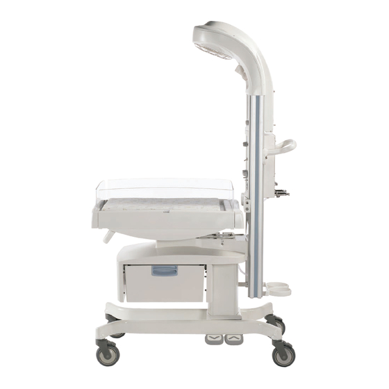
GE PANDA Infant Warmer Manuals
Manuals and User Guides for GE PANDA Infant Warmer. We have
1
GE PANDA Infant Warmer manual available for free PDF download: Service Manual
GE PANDA Service Manual (212 pages)
Warmers
Brand:
GE
| Category:
Medical Equipment
| Size: 24.22 MB
Table of Contents
Table of Contents
5
About this Manual
11
Scope and Intended Users
11
Conventions
11
User Responsibility
11
Important Safety Information
13
Warnings, Cautions, and Notes
14
Service Language Disclaimer
15
Symbols
23
Regulatory
24
Standards
24
Chapter 1: Functional Description
25
Introduction
25
Mechanical Controls and Cable Connections
28
Controls and Displays
31
Mechanical Modules
32
Heater Head Assembly
32
Rails
32
Optional Resuscitation Assembly (Bedded and Freestanding Only)
32
Probe Panel Assembly
32
Base Assembly (Bedded and Freestanding Only)
32
Bed Assembly (Bedded Only)
33
Optional In-Bed Scale (Bedded Only)
33
Giraffe Shuttle Accessory (Bedded Only)
33
System Functions
34
System Overview (Fully-Loaded Bedded Shown)
34
Hands Free Alarm Silence
35
Watchdog
35
Battery Management
36
Power Fail
37
External Communication
39
Service Mode
40
Display
40
Touch Panel
40
Elevating Base (Bedded Models Only)
41
Observation Lights
42
Procedure Light (Optional on Panda Warmer)
42
Heat Control
43
Scale (Bedded Models Only)
47
Alarms
48
Equipment Grounding
49
AC/DC Power Distribution
50
Serial Data
51
Connector
51
Data Stream
51
Nurse Call
52
Chapter 2: Installation, Maintenance, and Checkout
53
Warmer Maintenance Schedule
53
Operator Maintenance
53
Service Maintenance
53
Installation and Service Checkout Procedures
54
Mechanical Checks
54
Controller Checks (Figure E-2)
55
Electrical Safety Tests
56
Mounting the Universal Adapter Plate
57
Scale Checkout Procedures
58
Visual Inspection
58
Center Weight Check
58
Off Center Weight Check
58
Load Cell Check
59
Chapter 3: Calibration
61
Scale Calibration (Bedded Models Only)
61
Chapter 4: Troubleshooting
63
Service Mode
63
Unit Information
63
Main Menu
63
Unit Info Menu
64
Operation Settings
65
Scale Calibration
66
Date/Time
67
Diagnostics
68
Odometer Readings
71
Event Logs
72
Set Defaults
74
Heat Engine Diagnostic
75
PC Command Line Interface
75
Accessing the PC Command Line Interface
75
PC Command Line Interface Main Menu
76
PC Command Line Interface Sub-Menus
77
Engineering Log Dump
80
Troubleshooting Information
83
Troubleshooting Tables
84
Lighting - Procedure Light
84
Lighting - Observation Lights
86
Display - LCD and Backlights
89
User Interface - Touch Panel
91
System Failure - Sys Fail Message
91
Alarms/Indicators
97
Electronics - Patient Temperature Probe
99
Electronics - Scale (Bedded Models Only)
100
Electronics – Spo2
101
Electronics - Elevating Base (Bedded Models Only)
102
Electronics - Heat Control
104
Electronics - Power Failure
104
Mechanical (Bedded Models Only)
105
Troubleshooting Definitions and Acronyms
106
Chapter 5: Repair Procedures
107
Common Hand Tools
107
Heater Head Removal from Wall Bracket (Wall Mount Only)
108
Heater Housing Repairs
108
Upper Heater Housing Removal
108
Heat Engine Assembly Removal
109
And Figure 5-5)
109
Heater Alignment Procedure
111
Power Supply Replacement (Figure 5-1)
114
Alarm Light Board Replacement (Figure 5-6 and Figure 5-8)
114
Replacing an Observation Light Bulb
115
Replacing the Procedure Light Bulb
116
Electronic Enclosure Repairs
116
Power Board (Figure 5-6 and Figure 5-7)
116
Control Board (Figure 5-6 and Figure 5-7)
117
Lithium-Ion Battery Replacement (Figure 5-6 5.4.4 Touch Panel or LCD Assembly (Figure 5-7 5.4.5 Observation Light Dimmer Control (Figure 5-8)
117
Lithium-Ion Battery Replacement (Figure 5-6 and Figure 5-7)
117
Touch Panel or LCD Assembly (Figure 5-7 and Figure 5-8)
118
Standby Switch Replacement (Figure 5-8)
119
Outlet Panel Repairs (Figure 5-9)
120
F7 and F8 Fuse Replacement Instructions
121
Maneuvering Handle
121
Probe Panel Housing Repairs
122
Probe Panel Housing Disassembly (Figure 5-10 and Figure 5-11)
122
Spo2 Interface Board Replacement
122
As Appropriate)
123
Spo2 Connector/Flex Circuit Replacement (Figure 5-10 or Figure
123
Patient Probe Connector Replacement (Figure 5-10 or Figure
124
Scale Connector Replacement (Figure 5-10) (Bedded Models Only)
124
Probe Panel Upper Housing Replacement
125
Appearance Strip Replacement
126
Lower Unit Repairs (Bedded and Freestanding Models)
127
Elevating Column Replacement (Figure 5-14) (Bedded Models Only)
127
Foot Switches (Figure 5-14) (Bedded Models Only)
127
Removing the Bed (Figure 5-13) (Bedded Models Only)
127
Caster Replacement (Figure 5-14) (Bedded and Freestanding Models)
128
Adjusting Bed Height Using Manual Elevating Column (Bedded Model Only)
130
Base and Rail Mounting Block Replacement (Figure 5-14) (Freestanding Models Only)
131
Chapter 6: Illustrated Parts
133
Heater Housing
134
Electronics Enclosure
136
Probe Panel Housing
140
Base Assembly (Bedded Models Only)
142
Elevating Column Special Instructions
142
Bed Assembly (Bedded Models Only)
145
Storage Options (Bedded Models Only)
148
Freestanding Model Parts
150
Wall Mount Model Parts
151
FRU Wall Mount Warmer Bumper Kit (2063179-001) Content
152
FRU Wall Mount Warmer Bracket Kit (Language-Specific) Content
152
Harness List
153
Options
154
Optional Equipment
154
Replacement and Additional Parts
155
Spo2 Upgrade Kits
156
Giraffe Scale Parts
158
Panda Scale Parts
158
Power Cords
158
Labels
159
Labels on the Back of Giraffe Warmers or Panda Ires Warmers
159
Heater Grille Accessory Warning Label Set (Bedded Models)
160
Labels on Probe Panel Housing
161
Control Panel Labels (Not Shown, See Figure 1-4)
161
Labels on Freestanding Model
162
Labels on Wall Mount Model
164
Test Points
168
Control Board
168
Power Board
169
Wiring Diagrams
170
Appendix A: Specifications
173
Power Requirements and Accessory Outlets
173
Operating Environment
173
User Control Settings
173
Performance
174
Mechanical Specifications
175
Bedded
175
Freestanding
175
Wall Mount
175
Spo2 Specifications
176
Nellcor
176
Nellcor Spo2 Cables and Probes
177
Power Fail Recovery
177
Masimo
177
A.6.6 Power Fail Recovery
179
Appendix B: Electromagnetic Compatibility
181
Electromagnetic Compatibility (EMC) Guidance
181
Manufacturer's Guidance and Declaration Regarding Electronic Emissions
181
Manufacturer's Guidance and Declaration Regarding Electromagnetic Immunity
182
International Electronic Commission (IEC) Guidance and Manufacturer's Declaration Regarding Electronic Immunity
183
Recommended Separation Distance between Portable and Mobile RF Communications Equipment and the Warmer
184
Appendix C: Alarm Priorities
185
Appendix D: Troubleshooting
189
Service Mode (Application Software 1.0.9 and Earlier
189
Unit-Specific Information
189
Operator Settings
190
Calibration
191
Diagnostics Using Serial Port
191
File Capture
192
Appendix E: Installing Wall Mount Units
197
Pre-Installation Preparation
198
Wall Mount Bracket Installation
199
Bumper Installation (for Installations with Bassinets
202
Heater Head Installation and Heater Alignment
203
Mattress Height Label Installation (for Installations with Bassinets
206
Enclosure Dimensional Specification
207
Advertisement
Advertisement
Related Products
GE LOGIQ P3
GE LOGIQ P3 PRO
GE ProSeed Accell El
GE ProSpeed Advantage
GE ProSeed SA
GE Voluson P8
GE LOGIQ P5
GE LOGIQ P6 Pro Series
GE Voluson P6 BT18
GE DINAMAP PRO 400V2
GE Categories
Refrigerator
Ranges
Microwave Oven
Air Conditioner
Dishwasher
More GE Manuals
Login
Sign In
OR
Sign in with Facebook
Sign in with Google
Upload manual
Upload from disk
Upload from URL