Sign In
Upload
Manuals
Brands
GE Manuals
Medical Equipment
FL000090
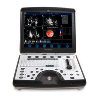
GE FL000090 Manuals
Manuals and User Guides for GE FL000090. We have
2
GE FL000090 manuals available for free PDF download: Service Manual
GE FL000090 Service Manual (483 pages)
Brand:
GE
| Category:
Medical Equipment
| Size: 12.93 MB
Table of Contents
Important Precautions
3
Legal Notes
11
List of Effected Pages (LOEP)
12
Revision History
12
Table of Contents
13
Dfl091021, R 4+10Jun09 Draft V Sm
26
Irection Fl091021, Revision 4+10Jun09 Draft IVID I Nervice Anual
26
CHAPTER 1 Introduction
27
Introduction
27
Overview
27
Purpose of Chapter 1
27
Purpose of Service Manual
28
Typical Users of the Service Manual
28
VIVID I N Models Covered in this Manual
28
System History - Hardware and Software Versions
29
Purpose of Operator Manual(S)
29
Icons
30
Important Conventions
30
Conventions Used in this Manual
30
Model Designations
30
Safety Precaution Messages
30
Standard Hazard Icons
31
Standard Icons Indicating a Special Procedure be Used
31
Safety Considerations
32
Human Safety
32
Mechanical Safety
32
Introduction
32
Electrical Safety
34
Probes
34
Dangerous Procedure Warnings
35
Explosion Warning
35
Product Labels and Icons
36
Label Descriptions
37
Product Icons VIVID I N
37
VIVID I N Battery Safety
39
VIVID I N External Labels
41
Rating Labels
41
EMC, EMI, and ESD
42
Electromagnetic Compatibility (EMC)
42
Electrostatic Discharge (ESD) Prevention
42
CE Compliance
42
Standards Used
43
Lockout/Tagout (LOTO) Requirements
44
Returning/Shipping Probes and Repair Parts
44
Customer Assistance
45
Contact Information
45
Phone Numbers for Customer Assistance
45
CHAPTER 2 Site Preparations
47
Overview
47
Purpose of Chapter 2
47
Console Requirements
48
Unit Environmental Requirements
48
Lighting Requirements
48
Time and Manpower Requirements
48
Electrical Requirements
49
VIVID I N Power Requirements
49
Inrush Current
49
Site Power Outlets
49
Mains Power Plug
50
Power Stability Requirements
50
EMI Limitations
50
Probe Environmental Requirements
51
EMI Prevention/ Abatement
51
Facility Needs
52
Purchaser Responsibilities
52
Mandatory Site Requirements
53
Site Recommendations
53
Recommended Ultrasound Room Layout
54
Networking Pre-Installation Requirements
55
Unit Connected to Hospital’s Network
55
Purpose of the DICOM Network Function
55
DICOM Option Pre-Installation Requirements
55
Connectivity Installation Worksheet
56
Site System Information
56
Check List
58
CHAPTER 3 System Setup
59
Overview
59
Purpose of Chapter 3
59
Installation Reminders
60
Average Installation Time
60
Installation Warnings
60
System Acclimation Time
60
Safety Reminders
61
The Tilt & Shock Indicators
62
Position of the Tilt & Shock Indicators
62
Tiltwatch and Shockwatch Positions on Transportation Box
62
Receiving the VIVID I N
63
Examin All Packages
63
Is Dammage Apparent?
63
Damage in Transportation
64
VIVID I N Transportation Box Label
65
Label Mounted
65
Unpacking the Equipment
66
Shipping Box for the VIVID in Only
66
To Remove the Lid of the Box
66
Contents in Transportation Box When Lid Is Removed
67
Examin All Packages
67
Shipping Carton Dimensions and Weights
67
Unpacked the VIVID I N
68
Unpacking the Wooden Transportation Box
68
EMI Protection
69
Physical Inspection
69
System Voltage Settings
69
Verifying the Transportation Box Contents
69
Preparing for Installation
70
Confirming Customer Order
70
Verifying the Transportation Box Contents
70
Component Inspection
71
Damage Inspection Checklist
71
Damage Inspection Checklist - VIVID I N System
71
Front and Side View of the VIVID in Ultrasound Unit
72
Rear View of the VIVID in Ultrasound Unit
73
Connection and Usage of the Optional Modo Cart
74
System Voltage Confirmation
75
Safety Rating Plate - Example
75
Ensuring Protection from EMI
76
Completing the Hardware Installation
77
Connecting Peripherals
77
USB Global Modem
77
Wireless Network Adaptor
78
DVD/CD-RW Drive
79
Samsung DVD/CD-RW Drive
79
DVD/CD-RW Drive Replacement on VIVID I N Systems
81
Parts to be Ordered
81
DVD/CD-RW Drive (Older Type)
82
MOD Drive
84
Connection Via USB Hub
84
Connection Directly to the VIVID I N System
84
USB Memory Stick
85
Connecting the Black & White Printer
86
Black and White Printer
86
Connecting the Digital Color Printer
87
Configuring Hot Keys to Activate Printing Direct from Control Panel
88
Configuring Control Panel Hot Keys for Printing
88
Connecting the Deskjet Color Printer
89
Deskjet Color Printer
89
Connecting the VCR
91
Video Casette Recorder
91
VGA Adaptor
91
Video Converter
91
Video Converter Dip Switches
92
Video Converter Dip Switch Positions
92
Single Icon
94
Confirm Desktop Change
94
Charging the Battery
95
Setting up the Charger
95
Battery Charger Unit
95
Battery Charger LED Indicators and Status
96
Recharge Time
96
Recalibration Time
96
Battery Recalibration
97
Connecting Probes
98
Probe Connection Locking Lever
98
Connecting the ECG
101
ECG Cables Connected to the ECG Connector Port
101
ECG Cable Types
101
Connecting the Unit to a Power Source
102
Connecting the Ultrasound Unit to the Electrical Outlet
102
Disconnecting the Ultrasound Unit from the Electrical Outlet
103
Switching the System ON/OFF
104
System Exit Dialog Box
104
Configuration
105
Configuration Procedures
105
Overview
105
Enter Location
106
Hospital and Department Name
106
Location Name
106
VIVID I N Configuration
106
Date and Time Adjustments
107
Language Adjustments
108
Language Selection
108
Select Units of Measure
109
Units of Measure
109
Open Service Screen
110
Service Screen (Example)
110
Service Screen Set-Up
110
Adjust Keyboard Backlight Intensity
111
Keyboard Light Intensity Adjustment
111
LCD Display Adjustment and Calibration
111
Select Keyboard Setup
111
Regional Options
112
Languages
113
Advanced
114
Add Printer
115
Add Printer Wizard
115
Select Add Printer
115
Configuring Peripherals
116
Approved Peripherals
116
Network Peripherals (Optional)
116
Virtual Printing (Optional)
117
Printers and Faxes Window
117
Virtual Printer Job Queue Window
117
Resuming Spooled Print Job
118
Software Options Configuration
119
Software Option Installation
119
On-Site Configuration
119
System Admin Screen
119
Connectivity Setup
120
Connectivity Introduction
120
Dataflow Naming Convention
120
Localarchive-MOD Dataflow
120
Dataflow Examples
121
Remotearch-Remotehd Dataflow
121
Examples of Dataflows
121
Stand-Alone VIVID I N
122
“Sneaker Net” Environment
122
VIVID I N and a DICOM Server in a Network
122
Physical Connection
123
Ethernet Switch Connections
123
Ethernet Switch Identifications
123
MDI Button Position Descriptions
123
Local Network Connection to Echopac PC Workstation
124
Hospital Network Connection to Echopac PC Workstation
124
Hospital Network Connections
124
Local Network Connection
124
Wireless Network Configuration
125
Network and Dial-Up Connections
125
Wireless Network Connection Dialog Box
126
CISCO_350 Sub-Directory
126
Connectivity Configuration
128
Select TCP/IP Set-Up Screen
128
Set the Scanner’s Network Information
129
Set the Remote Archive’s Network Information
129
Save the New Settings
130
Save New TCP/IP Settings
130
Configuring the VIVID I N and Network PC for Peer-To-Peer Connection
131
Connectivity Dialog Box - TCPIP Advanced Tab
131
Local Area Connection Properties
131
Internet Protocol (TCP/IP) Properties
132
Set up Connection to a DICOM Server in a Network
139
DICOM Server IP Address Setting on the Scanner
139
Select Worklist Properties Dialog Box
140
Search Criterias Window
141
Search Criterias Window - Updated
142
DICOM Server’s Properties Dialog Box
143
Setup Connection to HL7 Server in a Network
146
Configuration of Modality Worklist Services
146
Identify Dataflow to be Used
146
Configure the DICOM Worklist Service
146
Configure Search Criteria: Constrain Query by MRN
147
Assign DICOM Worklist Name to Dataflow
147
Configure Search Criteria: Constrain Query by AE Title
147
Configure the Export to HL7 Path
148
Troubleshoot Connectivity with the Gateway
148
Test Connectivity with the VIVID HL7 Gateway
148
Troubleshoot Connectivity with the VIVID HL7 Gateway
149
Query/Retrieve (Q/R) Setup
150
Query/Retrieve Setup on the VIVID in
150
Select Query Retrieve
150
Query/Retrieve Workflow
151
Select Query/Retrieve’s Properties
151
DICOM Query/Retrieve Properties
152
Change Search Criterias
153
Select Search Criterias
153
Query/Retrieve Verification
154
Check the DICOM Query/Retrieve Workflow
155
Test (Check) Passed
155
Test (Check) Failed
156
Mpegvue Export Configuration
157
Preparations
157
Configuring the VIVID I N for Mpegvue Export
158
Evue Properties
159
Evue Properties Dialog Box
159
Exporting to Mpegvue
160
Export Dialog Box
160
Evue Dataflow Configuration
162
Configuring the VIVID I N for Evue Dataflow
163
Connectivity - Dataflow Tab Selected
163
Using Mpegvue/Evue on a Remote PC
166
Installing Mpegvue on a Remote PC
166
Manually Setting the Network PC for Evue Import
169
User Accounts Dialog Box
169
Local Users and Groups Dialog Box
170
New User Dialog Box
170
Evue_Import Properties Dialog Box
172
Permissions for Evue Import Dialog Box
173
Select Users, Computers, or Groups Dialog Box
173
Manually Stopping the Firewall on the Network PC
176
Stopping an External Service Firewall
178
Administrative Tools Dialog Box
178
Services Dialog Box
179
Stopping the Firewall on Windows XP Service Pack 2
180
Windows Firewall Dialog Box
180
Un-Installing Mpegvue on a Remote PC
181
Uninstall Mpegvue - Stage 1
181
Deleting All Files
183
Using Mpegvue Viewer on a Remote PC
184
To Read Mpegvue Exams Stored on Other Media
184
Mpegvue Patient List
184
Mpegvue Screen
185
Selecting an Image
186
Stopping & Running the Cine-Loop
186
Selecting a Different Patient
186
Exporting Images or Loops from Mpegvue
186
Performing Measurements on Mpegvue Images
187
Saved Worksheets
187
Reports (.CHM Files)
187
Using Mpegvue over E-Mail
188
Sending a Full Examination by E-Mail
188
E-Mail Address Window
189
Enter Password Window
189
Sending Message to Outbox Progress Window
190
Sending an Image by E-Mail
191
Sending the Mpegvue Player Software by E-Mail
193
First Time Receipt of Mpegvue Player Software and Images by E-Mail
193
Warning Message
194
Managing and Viewing Exams Received
195
Mpegvue Startup Menu
195
Get New Exams by E-Mail
196
Start Mpegvue Screen
196
List of Studies Found in Inbox
197
Password Window
198
Message Showing Exams Being Deleted from Inbox
198
Receiving and Viewing a Partial Examination
199
View Previous Exams from E-Mail
200
Activate E-Vue
200
Using Patient Manager
201
Mpegvue Patient Manager Window
201
Exams Selected
202
Using Mpegvue Player
209
Image Review Window
210
Storing and Transporting the Unit
212
Transportation Box and Packaging Materials
212
Completing the Installation Paperwork
213
System Installation Details
213
Product Locator Installation
213
Product Locator Installation Card
214
User Manual(S)
215
CHAPTER 4 General Procedures and Functional Checks
217
Overview
217
Purpose of Chapter 4
217
Specific Equipment Required
218
General Procedures
219
Power On/Boot-Up
219
Connecting Mains Power to the VIVID I N Ultrasound Unit
219
Overview
219
Mains Power Connector - Rear Panel
220
Turning the System on
221
On/Off Button on Control Panel
221
Start-Up Progress Bar for VIVID in
222
2D Screen
222
Power Shut down
223
Standby
223
Logoff
223
Shutdown
223
Standby Mode
224
Complete Power down
225
Log on to the System as ADM
226
Logging on to the System as ADM 1 of 2
226
Using Removable Media
227
Install MO Disk in MO Drive
228
Eject and Remove MO Disk from MOD Drive
228
Installing DVD/CD into DVD/CD Drive
228
Eject Device Menu
228
Eject and Remove DVD/CD from DVD/CD Drive
229
Labeling Removable Media
229
Formatting Removable Media
229
Verifying Removable Media
230
Archiving and Loading Presets
230
Archiving Presets to an MO Disk
231
Saving Presets VIVID I N
231
Loading Presets from an MO Disk
232
Loading Presets VIVID
232
Functional Checks
233
Basic Controls
233
Alphanumeric Keyboard Test
233
Alphanumeric Keyboard Test - Recommended
233
External Keyboard Test VIVID
234
Trackball Test - Recommended
236
System ID Test
237
System ID Test - Recommended
237
CW Test - Recommended
237
Visual Test - Recommended
238
Peripherals
239
VCR Test
239
VCR Test - Recommended
239
B/W Printer Test - Recommended
239
Back End Processor Tests
240
Phono Test - Recommended
240
MOD Test VIVID I N - Recommended
240
DVD/CD Writer Test
241
Plug and Scan Test
243
Plug and Scan Test - Recommended
243
System Turnover Checklist
244
Software Configuration Checks
244
Software Configuration Checklist
244
Site Log
245
Components and Function (Theory)
247
General Information
247
Front and Side View of the VIVID I Nsystem
248
Signal Flow
249
System Configuration and Software
249
Operator Panel
249
Electronics
249
VIVID I N Systems - Block Diagram
250
Front End Unit
251
Scanner Subsystem
251
Front End Subsystem
251
VIVID I N System Block Diagram Showing Location of Front End
251
Front End Block Diagram
252
Probe & MUX
252
Front End Unit - Location in the System
253
Bottom Assembly Showing Location of Front End
253
Keyboard Assembly in Opened Position
253
Bottom Assembly Showing Position of Boards
254
RFI Board
255
Tasks Performed by the RFI Board
255
Watchdog and Power on Reset
255
Boot-Up of DSP and Firmware
255
FPGA Download
256
PCI Connection
256
RFI Board Connectors
257
RFI Board Connector Locations
257
RFI Board - Input DC Voltages
258
Probe Management
258
Mechanism
258
TR32 Boards (Transmitter/Receiver)
259
TR32 Board Block Diagram
259
Connectors on TR32 Board - Upper View
259
Connectors on TR32 Board - Bottom View
260
TR32 Board Connectors
260
TR32 Board - Input DC Voltages
260
TR32 Board - Stacked Connectors
261
Probe and MUX (P&M) Board
262
Probe and MUX Board - Block Diagram
262
Probe and MUX Board Connector Locations
263
Probe and MUX Board Connectors
263
P & M Board Input DC Voltages
264
Back End Processor
265
Location of BEP in Bottom Assembly
265
VIVID I N Back End Processor - Block Diagram
266
Abbreviations and Definitions
267
ETX SBC Central Processing Unit (CPU)
267
ETX Base Board
267
Overview of ETX Base Board Functions
267
VGA Interface
268
Cardbus Interface
268
ETX Base Board - Block Diagram
268
Hard Disk
269
Fan Control
269
RTC Battery
269
Location of Fan Board in the Bottom Assembly
269
Back End Processor - Location of Components
270
Views of the Back End Processor (BEP)
270
Upper View
270
Lower View
270
BEP Connectors
271
Connectors on the BEP
271
BEP Input DC Voltages
272
Left/Right Speakers
272
External Input/Output (I/O)
273
VIVID I Nsystem - Rear Panel Connections
273
Power Supply System
274
Electrical Power
274
Power Supply Unit Components
275
Critical Temperature Sensor
275
VIVID I N Power Supply Unit Components - Block Diagram
275
DC Source Selector
276
DC Source Selector Connectors
276
Rechargeable Battery Pack Assy (GPA)
277
Recommended Storage Conditions of Battery Pack
278
Monitor and Operator Panel
279
Keyboard and Operator Panel
279
VIVID I N System — Keyboard and Operator Panel Layout
279
VIVID I N Keyboard — Block Diagram
280
Keyboard and Operator Panel Components
281
Power ON/OFF Button
281
Alphanumeric Keyboard
281
TGC Sliders
281
Key and Backlight Illumination
282
USB Hub
282
Power Interface
282
Keyboard ID
282
Keyboard Connectors
283
LCD Display Unit
283
Keyboard Module Connectors
283
LCD Display - Flex Cable Connection to BEP
283
ECG Module
284
ECG Patient I/O Module
284
ECG Patient I/O Module - Block Diagram
284
ECG Patient I/O Module Specifications
285
Sample Rate
285
Bandwidth
285
Isolation
285
Printers
286
Black & White Digital Printer
286
DVD/CD Reader and CD Writer (DVD/CDR-W)
286
Magneto-Optical Drive (MOD)
286
Wireless Network Adapter
287
Cooling System
288
Air Flow through the VIVID I N Ultrasound Scanner
288
Service Adjustments
289
LCD Display Adjustments and Calibration
289
LCD Display Calibration Screen
290
Contrast Adjustment Procedure
291
Brightness Adjustment Procedure
291
LCD Display - Contrast Adjustment
291
LCD Display - Brightness Adjustment
291
Testing Your Contrast and Brightness Settings
292
Blue Tint Adjustment Procedure
292
LCD Display - V Watermark Adjustment
292
LCD Display - Blue Tint Adjustment
292
Deactiving the Screen-Saver When Using the DVD
293
Keyboard Adjustments
294
Video System Adjustments
294
Beamformer Calibration
294
Battery Calibration
295
Recommendations - Battery Calibration Procedure
295
Performing the Battery Calibration Procedure
296
Battery Calibration Wizard
296
Diagnostics/Troubleshooting
301
Diagnostic Tools
302
Diagnostic Procedure Summary
302
Accessing the Diagnostic Test Window
303
Diagnostic Test Window
303
VIVID I N Diagnostics Test Window and Menu Options
304
View Log
305
VIVID I N Diagnostics Test Window
305
View Log Dialog Box
307
ADC Test - Viewing Report
308
Diagnostic Test Window Menu Options
309
Full System Test (FE and BEP)
309
Performing Full System Diagnostics
310
Accessing the Full System Diagnostic Options
311
Full System (FE and BEP) Test
311
View Test Log - Full System Test (BEP and FE)
313
Calibration Tests
315
DC Offset Calibration
315
DC Offset Calibration Test
315
View Test Log - DC Offset Calibration
316
DC Offset Verification
318
DC Offset Verification Test
318
View Test Log - DC Offset Verification Test
319
Replacement Procedures
321
External Component Replacement Procedures
322
Battery Replacement Procedure
322
Battery Removal Procedure
322
Closing VIVID I N LCD Cover
322
Battery Installation Procedure
323
Hard Disk Replacement Procedure
324
Hard Disk Removal Procedure
324
Removing the Screws from the Rear Panel
324
Removing the Hard Disk
324
Hard Disk Installation Procedure
325
Control Panel and Keyboard Replacement Procedure
326
Tools
326
Control Panel and Keyboard Removal Procedure
326
Removing the Fastening Screws from the Bottom Assembly
326
Removing the Control Panel and Keyboard
327
Disconnecting the Control Panel/Keyboard Cable
327
Control Panel and Keyboard Installation Procedure
328
Keycap Removal Procedure
329
Keycap Installation Procedure
329
Keycap Replacement
329
Trackball Removal Procedure
330
Trackball Installation Procedure
330
ATGC Slider Keycap Removal Procedure
331
ATGC Slider Keycap Installation Procedure
331
ATGC Slider Keycap Replacement
331
ATGC Rotary Knob Removal Procedure
332
ATGC Rotary Knob Installation Procedure
332
ECG Module Assembly Removal Procedure
333
ECG Module Assembly Installation Procedure
333
Rear Cover & Latch Assembly Replacement Procedure
334
Rear Cover & Latch Assembly Removal Procedure
334
Removing the Hinge Screws
334
Rear Cover & Latch Assembly Installation Procedure
335
LCD Display Cover Hinges Replacement Procedure
336
LCD Display Cover Removal Procedure
336
LCD Flex Cable Connected to BEP
336
LCD Display Hinges Secured to Base Assembly - Location of Screws
337
Hinges Secured to LCD Display Cover - Location of Screws
338
Hinges Removed from LCD Display Cover
338
LCD Display Cover Installation Procedure
339
Bottom Assembly Replacement Procedure
340
Bottom Assembly Removal Procedure
340
Bottom Assembly Installation Procedure
341
LCD Display Frame Replacement Procedure
342
LCD Display Frame Removal Procedure
342
Removing the Screw Caps from the LCD Display Frame
342
Removing the Securing Screws
342
LCD Display Frame Installation Procedure
343
Removing the LCD Display Frame
343
Internal Component Replacement Procedures
344
P&M (Probe and MUX) Board Replacement Procedure
344
P&M (Probe and MUX) Board Removal Procedure
345
Removing the Screws that Secure the P&M Board to the RFI Board
345
Loosening the Screws from the P&M Board
345
Removing the Probe and MUX Board from the Bottom Assembly
346
P&M (Probe and MUX) Board Installation Procedure
346
TR32 and RFI Boards Replacement Procedure
347
Loosen Screws that Secure TR32 and RFI Boards to Bottom Assembly
347
Removing the Screws
348
Disconnecting the PCI Cable from the RFI Board
348
Disconnecting the DC Power Supply
349
Accessing the RFI and TR32 Boards
349
Removing the RFI and TR32 Boards from the Bottom Assembly
350
Removing the RFI Board from the TR32 Boards
350
Separating the Two TR32 Boards from each Other
351
TR32 and RFI Boards Installation Procedure
352
BEP Replacement Procedure
353
BEP Removal Procedure
353
Disconnecting Cables from the BEP
354
Removing the Screws from the BEP
355
Removing the BEP from the Bottom Assembly
355
BEP Installation Procedure
356
HVPS Replacement Procedure
358
HVPS Removal Procedure
358
Disconnecting the DC Power Supply Cables
358
Loosening the Screws on the DC Power Supply
359
Removing the DC Power Supply
359
HVPS Installation Procedure
360
Fan Replacement Procedure
361
Fan Removal Procedure
361
Removing the Screws from the Fan Assembly
361
Disconnecting the Speaker Cable
361
Removing the Fan Assembly
362
Disconnecting the Fan Cable from the BEP
362
Fan Installation Procedure
363
Speaker Assembly Replacement Procedure
364
Speaker Assembly Removal Procedure
364
Speaker Assembly Installation Procedure
364
LCD Display Replacement Procedure
365
Removing the Screws from the LCD Display
365
Disconnecting the LCD Flex Ribbon Cable
366
Removing the LCD Display
366
LCD Display Installation Procedure
367
Selecting Setlcdtype Utility
368
Set LCD Type Dialog
368
Selecting LCD Type Installed on the System
369
LCD Flex Cable Replacement Procedure
370
LCD Flex Cable Removal Procedure
370
Flex Cable Replacement Procedure
372
Connecting the Flex Cable to the LCD Rear Panel
372
Adhering Kapton Tape on the LCD Rear Panel Connector
373
Microphone Assembly Replacement Procedure
374
Microphone Assembly Removal Procedure
374
Releasing the Microphone
374
Disconnecting the Miniature Plug
374
Microphone Assembly Installation Procedure
375
Software Loading
376
Software Installation/Upgrade Procedure Overview
376
VIVID I N Software Upgrade from Version BT06 to BT09
377
VIVID I N Software Upgrade (BT06 to BT09) Procedure
379
VIVID I N Software Re-Installation/Upgrade
382
Setting the BIOS
388
BIOS Main Tab
388
Setting the BIOS Advanced Parameters
389
BIOS Advanced Parameters Screen
389
BIOS Advanced Chipset Control Parameters
390
BIOS Advanced PCI/PNP Parameters
390
BIOS Advanced Memory Cache Parameters
391
BIOS Advanced I/O Device Configuration Parameters
392
BIOS Advanced Keyboard Features Parameters
392
BIOS Advanced Hardware Monitor Parameters
393
BIOS Advanced Watchdog Settings
393
BIOS Advanced Display Control Parameters
394
BIOS Advanced Miscellaneous Parameters
395
Additional BIOS Settings
396
BIOS Security Parameters
396
BIOS Power Parameters
397
BIOS Boot Parameters
397
BIOS Exit Screen
398
BIOS Firmware Update
399
BIOS Update in Progress
400
Boot-Up Screen after Completion of BIOS Update
401
Formatting and Partitioning the Hard Disk - Automatic Procedure
402
Formatting and Partitioning the Hard Disk - Manual Procedure
404
Partition Magic Screen
405
Operations Menu
405
Full Re-Ghost and Software Installation
408
Installing Software Only from DVD
410
Start Application Screen
411
Start Software Installation Message
411
Installing Software Only or Patch
415
VIVID I Nsoftware Roll-Back Procedure
416
Software Roll-Back Procedurevivid I N 1 of 2
416
Performing a Complete System Back-Up
418
Database Merge
418
How to Restore User-Defined Presets
418
Modo Cart Components Replacement
421
Replace the Cable Clips
422
Removing the Cable Clips
422
Installing the Cable Clips
422
Pinch Together the Cable Clips
422
Fuses Replacement
423
Fuses - Removal Procedure
423
Open Fuse Protection on Rear of Transformer
423
Change Fuses of Isolation Transformer
423
Fuses - Installation Procedure
424
Replace the Isolation Transformer
425
Removing the Isolation Transformer
425
Remove Screws
425
Disconnect the Ground Cable
425
Installing the Isolation Transformer
426
Replace the Wheels
427
Removing the Wheels
427
Installing the Wheels
427
Screw off the Wheels
427
Renewal Parts
429
List of Abbreviations
430
Mechanical Hardware Parts
431
Electronic Parts
432
Cables
434
Optional Modo Cart
439
Modo Cart - Replacement Parts
439
VIVID I N Spare Part Kits
440
Product Manuals
443
Care and Maintenance
445
Periodic Maintenance Inspections
445
Warnings
446
Why Perform Maintenance Procedures?
447
Quality Assurance
447
Maintenance Task Schedule
448
Tools Required
450
Special Tools, Supplies and Equipment
450
Specific Requirements for Care & Maintenance
450
System Maintenance
452
Preliminary Checks
452
System Preliminary Checks
452
System Checks
453
System Functional Checks
453
Peripheral/Option Checks
454
Input Power Checks
454
Mains Cable Inspection
454
GE Approved Peripheral/Hardware Option Functional Checks
454
General Cleaning
455
VIVID I N System - General Cleaning
456
Probe Maintenance
459
Probe Checks
459
Probe Handling
459
Basic Probe Care
460
Probe Cleaning
460
General Probe Cleaning Instructions
461
Cleaning and Sterilizing Probes Used Externally
462
Cleaning & Sterilizing Procedure for Probes Used Externally
462
Cleaning and Sterilizing Probes Used Internally
462
Returning and Shipping of Defective Probes
463
Electrical Safety Tests
464
Safety Test Overview
464
GEHC Current Leakage Limits
465
Chassis Current Leakage Limits - Accessible Metal Surfaces
465
Typical Outlet Tester
466
Grounding Continuity
467
Ground Continuity Test
467
Meter Procedure
467
Dale 600 - Ground Continuity (Systems with Modo Cart)
468
Dale 600 Ground Continuity Test
468
Chassis Current Leakage Test
469
Generic Procedure
469
VIVID I Nvivid I Ndata Sheet for Chassis Source Current Leakage
470
Isolated Patient Lead (Source) Leakage – Lead-To-Ground
471
Test Circuit for Measuring Non-Isolated Patient Leads
471
Data Sheet for ECG Current Leakage
473
Maximum Allowance Limit for ECG Lead Leakage Test to Ground
473
Maximum Allowance Limit for ECG Lead Isolation Sink Test
473
Typical Data Sheet for ECG Lead-To-Lead Test
473
Probe Current Leakage Test
474
Set up for Probe Current Leakage Test
474
VIVID I Nno Meter Probe Adapter Procedure
475
Check Without Probe Adapter
475
Data Sheet for Transducer Source Current Leakage
476
Typical Data Sheet for Transducer Source Current Leakage Test
476
Excessive Current Leakage
477
Possible Causes of Excessive Current Leakage
477
Chassis Fails
477
Probe Fails
477
VIVID I N Inspection Certificates
478
Advertisement
GE FL000090 Service Manual (740 pages)
Brand:
GE
| Category:
Medical Equipment
| Size: 45.83 MB
Table of Contents
Table of Contents
15
CHAPTER 1 Introduction
31
CHAPTER 2 Site Preparations
31
Overview
31
Purpose of Chapter 1
31
Purpose of Service Manual
32
Typical Users of the Service Manual (this Manual)
32
VIVID I N Models Covered in this Manual
33
VIVID Q N Models Covered in this Manual
33
System History - Hardware and Software Versions
34
Purpose of Operator Manual(S)
34
Important Conventions
35
Conventions Used in this Manual
35
Safety Considerations
37
Introduction
37
Human Safety
37
Mechanical Safety
37
Electrical Safety
39
Dangerous Procedure Warnings
41
Product Labels and Icons
42
Universal Product Labels
42
Label Descriptions
44
VIVID I N/ VIVID Q N Battery Safety
47
VIVID I N and VIVID Q N External Labels
49
Safelock Cart Labels
50
EMC, EMI, and ESD
51
Electromagnetic Compatibility (EMC)
51
CE Compliance
51
Electrostatic Discharge (ESD) Prevention
51
Standards Used
52
Lockout/Tagout (LOTO) Requirements
53
Returning/Shipping Probes and Repair Parts
54
Customer Assistance
55
Purpose of Chapter 2
57
Console Requirements
58
Unit Environmental Requirements
58
Cooling Requirements
58
Lighting Requirements
58
Time and Manpower Requirements
58
Electrical Requirements
59
EMI Limitations
60
Probe Environmental Requirements
61
Facility Needs
62
Purchaser Responsibilities
62
Mandatory Site Requirements
63
Site Recommendations
63
Networking Pre-Installation Requirements
65
Connectivity Installation Worksheet
66
Check List
68
CHAPTER 3 System Setup
69
Overview
69
Purpose of Chapter 3
69
Installation Reminders
70
Average Installation Time
70
Installation Warnings
70
Safety Reminders
71
The Tilt & Shock Indicators
72
Damage in Transportation
74
Unpacking the Equipment
77
Examin All Packages
78
Unpacking the Wooden Transportation Box
79
Verifying the Transportation Box Contents
80
Physical Inspection
80
EMI Protection
80
Preparing for Installation
81
Confirming Customer Order
81
Verifying the Transportation Box Contents
81
Component Inspection
82
Confirming Safelock Cart Voltage Configuration
87
System Voltage Confirmation
87
Ensuring Protection from EMI
88
Completing the Hardware Installation
89
Connecting Printers
89
Connecting Peripherals
102
Charging the Battery
123
Connecting Probes
126
Connecting the ECG
129
Connecting the Unit to a Power Source
130
Switching the System ON/OFF
132
Mounting the VIVID I N/ VIVID Q N on the Safelock Cart (Optional)
133
Mounting the VIVID I N and VIVID Q N on the Safelock Cart
133
Direction Fq091013, Revision
134
Adjusting the Safelock Cart Locking Mechanism
136
Configuration
137
Overview
137
VIVID I N/ VIVID Q N Configuration
138
Service Screen Set-Up
143
Configuring Peripherals
149
Software Options Configuration
152
Connectivity Setup
153
Connectivity Introduction
153
Physical Connection
156
Connectivity Configuration
166
Set up Connection to a DICOM Server in a Network
178
Setup Connection to HL7 Server in a Network
185
Query/Retrieve (Q/R) Setup
188
Mpegvue Export Configuration
195
Evue Dataflow Configuration
200
Using Mpegvue/Evue on a Remote PC
204
Storing and Transporting the Unit
245
Safety Precautions for Moving the VIVID I N/ VIVID Q N Unit
245
Transportation Box and Packaging Materials
245
Completing the Installation Paperwork
246
System Installation Details
246
Product Locator Installation
246
Product Locator Installation Card
247
User Manual(S)
248
CHAPTER 4 General Procedures and Functional Checks
249
Overview
249
Purpose of Chapter 4
249
Specific Equipment Required
250
General Procedures
251
Overview
251
Power On/Boot-Up
251
Power Shut down
255
Log on to the System as ADM
258
Using Removable Media
260
Labeling Removable Media
263
Formatting Removable Media
263
Verifying Removable Media
264
Archiving and Loading Presets
265
Functional Checks
267
Basic Controls
267
Peripherals
276
Safelock Cart Functional Tests
281
Back End Processor Tests
282
System Turnover Checklist
285
Software Configuration Checks
285
Site Log
286
CHAPTER 5 Components and Function (Theory)
289
Overview
289
Purpose of Chapter 5
289
General Information
290
Introduction
290
Signal Flow
292
VIVID I N and VIVID Q N Systems - Block Diagram
293
Front End Unit
294
General Information
294
Front End Unit - Location in the System
297
RFI Board
299
TR32 Boards (Transmitter/Receiver)
303
Probe and MUX (P&M) Board
306
Back End Processor
309
Introduction
309
ETX SBC Central Processing Unit (CPU)
311
ETX Base Board
311
Hard Disk
313
Fan Control
313
RTC (BIOS) Battery
313
Back End Processor - Location of Components
314
Left/Right Speakers
316
External Input/Output (I/O)
317
Power Supply System
318
Electrical Power
318
Introduction
318
Power Supply Unit Components
319
DC Source Selector
319
Rechargeable Battery Pack Assy (GPA)
320
Monitor and Operator Panel
322
Keyboard and Operator Panel
322
Keyboard and Operator Panel Components
323
ECG Module
327
Overview
327
ECG Patient I/O Module Specifications
328
Isolation
328
Ecg/Respiratory Module
329
Internal Ecg/Respiratory Board
329
External Ecg/Respiratory Interface
331
Peripherals
334
Introduction
334
Cooling System
336
General Information
336
CHAPTER 6 Service Adjustments
337
Overview
337
Purpose of Chapter 6
337
LCD Display Adjustments and Calibration
338
Contrast Adjustment Procedure
338
Brightness Adjustment Procedure
339
Testing Your Contrast and Brightness Settings
339
Blue Tint Adjustment Procedure
339
Blue Tint "2" Adjustment Procedure
341
External Monitor Calibration
344
Keyboard Adjustments
346
Configuring Print Orientation
346
Video System Adjustments
346
Beamformer Calibration
346
Battery Calibration
347
CHAPTER 7 Diagnostics/Troubleshooting
353
Overview
353
Purpose of Chapter
353
Diagnostics
354
Diagnostic Tools
354
Diagnostic Procedure Summary
354
Accessing the Diagnostic Test Window
355
Diagnostic Test Window Menu Options
362
Performing Full System Diagnostics
371
Accessing the Full System Diagnostic Options
372
Performing Front End (FE) Diagnostics
376
Accessing the Front End Diagnostic Options
377
Calibration Tests
377
Radio Frequency Interface (RFI) Diagnostic Tests
383
TR 32 Diagnostic Tests
398
Probe and MUX Diagnostic Tests
413
Monitoring Tests
438
Accessing the Monitoring Diagnostic Test Options
438
Performing Back End Diagnostics on the System
460
Accessing the Back End Diagnostic Test Options
460
Insite Exc
489
Service Desktop
489
Error Logs Page
491
Diagnostics Page
496
Image Quality Page
503
Calibration Page
503
Configuration Page
504
Ziputilities Page
505
Replacement Page
517
PM Page
517
Automatic Error Log
518
Adding Bookmarks
518
Extracting Logs
518
CHAPTER 8 Replacement Procedures
529
Overview
529
External Component Replacement Procedures
531
Bearing Handle Replacement Procedure
531
Battery Replacement Procedure
533
Hard Disk Replacement Procedure
535
Control Panel and Keyboard Replacement Procedure
537
Rear Cover & Latch Assembly Replacement Procedure
547
LCD Display Cover Hinges Replacement Procedure
549
Bottom Assembly Replacement Procedure
553
LCD Display Frame Replacement Procedure
555
Internal Component Replacement Procedures
557
TR32 and RFI Boards Replacement Procedure
560
BEP Replacement Procedure
566
BIOS Battery Replacement
573
HVPS Replacement Procedure
574
Fan Replacement Procedure
577
Speaker Assembly Replacement Procedure
580
LCD Display Replacement Procedure
581
LCD Flex Cable Replacement Procedure
586
Safelock Cart Components Replacement
589
Overview of Safelock Cart Replaceable Components
590
Safelock Cart Replacement Procedures - Quick Reference List
591
Upper Cover (Rear) Replacement Procedure
592
AC Cable Hook Replacement Procedure
593
AC Power Cable Bumper Protector Replacement Procedure
594
ECG Cable Protector Replacement Procedure
596
Lower Cover (Rear) Replacement Procedure
599
AC Distribution Assembly Replacement Procedure
600
Peripheral Power Cable Replacement Procedure
602
Main Cable Harness Replacement Procedure
607
USB Board Replacement Procedure
608
Gas Spring Replacement Procedure
610
DVD Holder Replacement Procedure
613
LAN Isolation Box and Holder Replacement Procedure
614
Top Shelf Replacement Procedure
615
Handrest Replacement Procedure
617
Probe Shelf Assembly Replacement Procedure
618
Probe Cable Hook Replacement Procedure
620
Front Wheel Replacement Procedure
621
Rear Wheel Replacement Procedure
623
Software Loading
625
Software Upgrade Procedure Overview
625
Setting the BIOS
636
BIOS Firmware Update
646
Formatting and Partitioning the Hard Disk - Automatic Procedure
649
Formatting and Partitioning the Hard Disk - Manual Procedure
651
Full Re-Ghost and Software Installation
656
Installing Software Only from DVD
658
Installing Software Only or Patch
662
Installation of PMC Version
663
Software Roll-Back Procedure
667
Performing a Complete System Back-Up
669
Database Merge
669
How to Restore User-Defined Presets
675
Peripherals
676
External USB Hard Disk Replacement Procedure
678
Advertisement
Related Products
GE FL000110
GE Fluorostar
GE FQ000040
GE FK000040
GE FK000060
GE FK000070
GE FK000196
GE FK000210
GE FK000220
GE FK000320
GE Categories
Refrigerator
Ranges
Microwave Oven
Air Conditioner
Dishwasher
More GE Manuals
Login
Sign In
OR
Sign in with Facebook
Sign in with Google
Upload manual
Upload from disk
Upload from URL