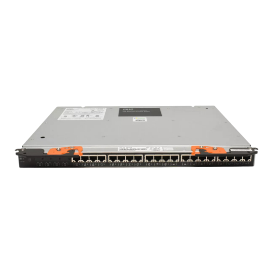
IBM Flex System EN2092 User Manual
1 gb ethernet scalable switch
Hide thumbs
Also See for Flex System EN2092:
- User manual (50 pages) ,
- Quick manual (30 pages) ,
- Quick start manual (2 pages)
Table of Contents
Advertisement
Quick Links
Advertisement
Table of Contents

Summary of Contents for IBM Flex System EN2092
- Page 1 IBM Flex System EN2092 1 Gb Ethernet Scalable Switch User's Guide...
- Page 3 IBM Flex System EN2092 1 Gb Ethernet Scalable Switch User's Guide...
- Page 4 Note: Before using this information and the product it supports, read the general information in Appendix B, “Notices,” on page 35, the Safety Information and Environmental Notices and User Guide documents on the IBM Notices for Network Devices CD, and the Warranty Information document that comes with the product.
-
Page 5: Table Of Contents
UL Regulatory Information..... viii Chapter 1. The IBM Flex System EN2092 1 Gb Ethernet Scalable Switch . . 1 Related documentation ..... . 1 Notices and statements in this document . - Page 6 Hardware service and support ....33 IBM Taiwan product service ....33 Appendix B.
-
Page 7: Safety
Prima di installare questo prodotto, leggere le Informazioni sulla Sicurezza. Les sikkerhetsinformasjonen (Safety Information) før du installerer dette produktet. Antes de instalar este produto, leia as Informações sobre Segurança. Antes de instalar este producto, lea la información de seguridad. © Copyright IBM Corp. 2013... -
Page 8: Safety Statements
Läs säkerhetsinformationen innan du installerar den här produkten. Bu ürünü kurmadan önce güvenlik bilgilerini okuyun. Safety statements Important: Each caution and danger statement in this document is labeled with a number. This number is used to cross reference an English-language caution or danger statement with translated versions of the caution or danger statement in the Safety Information document. - Page 9 DANGER Electrical current from power, telephone, and communication cables is hazardous. To avoid a shock hazard: v Do not connect or disconnect any cables or perform installation, maintenance, or reconfiguration of this product during an electrical storm. v Connect all power cords to a properly wired and grounded electrical outlet.
-
Page 10: Ul Regulatory Information
Laser radiation when open. Do not stare into the beam, do not view directly with optical instruments, and avoid direct exposure to the beam. UL Regulatory Information This device is for use only with Listed IBM Flex System Enterprise Chassis. viii EN2092 1 Gb Ethernet Scalable Switch: User's Guide... -
Page 11: Chapter 1. The Ibm Flex System En2092 1 Gb Ethernet Scalable Switch
IBM Flex System EN2092 1 Gb Ethernet Scalable Switch ISCLI—Industry Standard CLI Command Reference v IBM Flex System EN2092 1 Gb Ethernet Scalable Switch BBI Quick Guide v IBM Flex System EN2092 1 Gb Ethernet Scalable Switch Release Notes v IBM Flex System Network Devices Basic Troubleshooting Information ©... -
Page 12: Notices And Statements In This Document
For detailed information about the switch hardware and firmware features, specifications, and standards, see the switch Application Guide. See the documentation that came with your IBM chassis for information about the environmental conditions and specifications that are supported by the system. -
Page 13: Chapter 2. Installing And Removing The Switch Module
I/O bay locations and the components that can be installed in them that is specific to your IBM Flex System chassis type. You can install up to four I/O modules in the IBM Flex System chassis, including Ethernet switch modules, Fibre Channel switch modules, Infiniband, and pass-thru modules (optical and copper). -
Page 14: Before Installing The Switch Module
3 or 4, a corresponding adapter card is required to be installed in each compute node to access the I/O bay. v The compute nodes or IBM Flex System chassis that are described or shown in this document might be different from your compute nodes or IBM Flex System chassis. -
Page 15: Installation Guidelines
You do not have to turn off the IBM Flex System chassis to install or replace any of the hot-swap modules on the front or rear of the IBM Flex System chassis. -
Page 16: Handling Static-Sensitive Devices
2 seconds. This drains static electricity from the package and from your body. v Remove the device from its package and install it directly into the IBM Flex System chassis without setting down the device. If it is necessary to set down the device, put it back into its static-protective package. - Page 17 5. 2. Verify that the switch is compatible with the chassis. For a list of supported optional devices for the IBM Flex System chassis and other IBM products, see http://www.ibm.com/servers/eserver/serverproven/compat/us/. 3. Select I/O bay in which to install the switch.
-
Page 18: Removing And Replacing The Switch Module
SFP+ module” on page 9, the documentation that comes with the cables, and the optional network devices to which the cables have been connected. For the locations of the connectors on the IBM Flex System chassis, see the documentation that comes with the IBM Flex System chassis. Then, continue with step 3. -
Page 19: Cabling The Switch Module And The Sfp+ Module
SFP+ module,” the documentation that comes with the cables, and the optional network devices to which the cables have been connected. For the locations of the connectors on the IBM Flex System chassis, see the documentation that comes with the IBM Flex System chassis. Then, continue with “Installing and removing the 10 Gb SFP+ module”... -
Page 20: Disconnecting The Sfp+ Module Cable
Fiber-optic cable Protective cap 2. Gently slide the fiber optic cable into the SFP+ module until it clicks into place. 3. Check the LEDs on the switch. When the switch is operating correctly, the green link LED is lit. For information about the status of the switch LEDs, see “Locating the information panels, LEDs, and external ports”...


