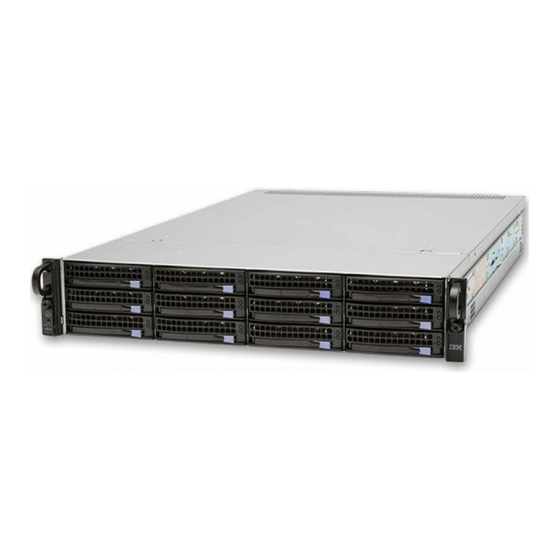
IBM AC922 Quick Install Manual
Hide thumbs
Also See for AC922:
- Installing (138 pages) ,
- Quick install manual (26 pages) ,
- Quick install manual (18 pages)
Advertisement
Quick Links
Advertisement

Summary of Contents for IBM AC922
- Page 1 IBM Power System AC922 (8335-GTG or 8335-GTH) Quick Install Guide...
- Page 2 ® ™ This 2020-03-11 edition applies to IBM Power Systems servers that contain the POWER9 processor and to all associated models. © Copyright International Business Machines Corporation 2017, 2020. US Government Users Restricted Rights – Use, duplication or disclosure restricted by GSA ADP Schedule Contract with...
- Page 3 Read all precautions and instructions before you start working on the system and its parts. Use normal electrostatic discharge (ESD) procedures when working on the system and parts. IBM recommends wearing gloves and an ESD wrist strap to avoid possible damage to the equipment.
- Page 4 2 IBM Power System AC922 (8335-GTG or 8335-GTH) Quick Install Guide...
- Page 5 Parts Use this information to find the field-replaceable unit (FRU) part numbers. Figure 1. Rack final assembly © Copyright IBM Corp. 2017, 2020...
- Page 6 Figure 2. System parts 4 IBM Power System AC922 (8335-GTG or 8335-GTH) Quick Install Guide...
- Page 7 Figure 3. Additional system parts (8335-GTC, 8335-GTG, or 8335-GTH air-cooled system) Parts 5...
- Page 8 Figure 4. Additional system parts (8335-GTW or 8335-GTX water-cooled system with 4 GPUs) 6 IBM Power System AC922 (8335-GTG or 8335-GTH) Quick Install Guide...
- Page 9 Figure 5. Additional system parts (8335-GTW or 8335-GTX water-cooled system with 6 GPUs) Parts 7...
- Page 10 8 IBM Power System AC922 (8335-GTG or 8335-GTH) Quick Install Guide...
-
Page 11: Rear Ports
Intelligent Platform Management Interface (IPMI) serial Ethernet. Use the top Ethernet port for the BMC/ IPMI interface (as PHY0). Use the bottom Ethernet port for any direct operating system usage (as PHY1). USB 3.0 © Copyright IBM Corp. 2017, 2020... - Page 12 10 IBM Power System AC922 (8335-GTG or 8335-GTH) Quick Install Guide...
- Page 13 Installing and removing parts Figure 7. Removing the power supplies from the system Figure 8. Removing the cover Figure 9. Disk drive lock detail Figure 10. Removing a fan from the system © Copyright IBM Corp. 2017, 2020...
- Page 14 Figure 11. Removing the disk and fan signal cable Figure 12. Removing the fan power cable from the system Figure 14. Screw locations for the disk drive and fan card Figure 13. Removing the front holder 12 IBM Power System AC922 (8335-GTG or 8335-GTH) Quick Install Guide...
- Page 15 Figure 15. Removing the disk drive and fan card Figure 16. Remove eight GPU screws per GPU; do Figure 17. Replacing the GPU and heat sink into not loosen the four spring-loaded screws system backplane Installing and removing parts 13...
- Page 16 Figure 19. Location of the memory modules Figure 18. Removing a memory module Figure 20. Removing the time-of-day battery from the system backplane 14 IBM Power System AC922 (8335-GTG or 8335-GTH) Quick Install Guide...
- Page 17 Figure 21. Removing a PCIe adapter Figure 22. Removing the BMC card Figure 24. Removing the rack installation support Figure 23. Removing the USB cable and the power switch and cable from the system backplane and the disk drive and fan card Installing and removing parts 15...
- Page 18 Figure 25. Remove the top and side screws Figure 26. Pull out the power switch and cable Figure 27. Removing USB cable and connector from the power switch 16 IBM Power System AC922 (8335-GTG or 8335-GTH) Quick Install Guide...
- Page 19 Figure 28. Remove the middle support side screws Figure 29. System backplane screw locations Figure 30. Lifting out the system backplane Installing and removing parts 17...
- Page 20 Figure 32. Removing dust and debris from the system processor module area Figure 33. Lowering the removal tool onto the Figure 34. Locking the system processor module system processor module into the tool 18 IBM Power System AC922 (8335-GTG or 8335-GTH) Quick Install Guide...
- Page 21 Figure 36. Inspecting the thermal interface material Figure 35. Placing the tool at an angle on the top cover of the packaging If the thermal interface material is damaged, replace it. Figure 38. Installing the heat sink on the gray- colored TIM Figure 37.
- Page 22 Figure 39. Tightening the center load screw on the heat sink 20 IBM Power System AC922 (8335-GTG or 8335-GTH) Quick Install Guide...
- Page 24 IBM®...


