Sign In
Upload
Manuals
Brands
Siemens Manuals
Servo Drives
SINAMICS S210
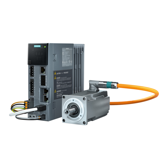
Siemens SINAMICS S210 Servo Drive System Manuals
Manuals and User Guides for Siemens SINAMICS S210 Servo Drive System. We have
3
Siemens SINAMICS S210 Servo Drive System manuals available for free PDF download: Operating Instructions Manual
Siemens SINAMICS S210 Operating Instructions Manual (769 pages)
Servo drive system
Brand:
Siemens
| Category:
Servo Drives
| Size: 12.2 MB
Table of Contents
Qualified Personnel
4
Preface
5
Technical Support
6
Use of Openssl
6
Table of Contents
7
Warning Notice System
4
1 Fundamental Safety Instructions
13
General Safety Instructions
13
Equipment Damage Due to Electric Fields or Electrostatic Discharge
19
Warranty and Liability for Application Examples
20
Industrial Security
21
Residual Risks of Power Drive Systems
22
2 Description
23
Correct Usage
23
Typical Applications
23
System Overview
24
System Components and Accessories
25
Converter
26
MOTION-CONNECT Cable (OCC Cable)
26
Motor
26
The Scope of Supply for the System Components
26
Cooling
27
Degree of Protection
27
Dynamic Versions
27
Motor
27
Power Range
27
Bearing Version
28
Encoder
28
Holding Brake
28
Shaft Extension (IEC 60072-1)
28
Rating Plate
29
Communicating with the Controller Via PROFINET
30
Control Mode
30
Converter
30
Integrated Braking Resistor
30
Integrated Safety Functions
30
Commissioning, Diagnostics and Data Backup
31
Rating Plate and Information Plate
31
Information Plate of the Converter
32
Connection Systems
33
Motor-Converter Combinations
34
Optional Accessories
35
3 Configuring
37
EMC-Compliant Installation of a Machine or System
37
Control Cabinet
37
Cables
38
Cable Routing Inside the Cabinet
38
Routing Cables Outside the Control Cabinet
39
Routing Converter Cables Inside and Outside a Control Cabinet
39
Electromechanical Components
40
Requirements Relating to Shielded Cables
40
Surge Voltage Protection Circuit
40
Permissible Line Supplies and Connection Options
41
Converter Operated on an IT System
41
Connection Options, 230 V Devices
42
Basic Connection Options
42
Connection Examples and Cable Cross-Sections
44
Connection Example for 400 V 3 AC
45
Configuring the Motor
46
Configuration Sequence
46
Motion Control
46
General Configuring Procedure
46
Clarification of Type of Drive
47
Limiting Characteristic for Synchronous Motors 1FK2
48
Specification of the Supplementary Conditions and Integration into the Automation System
48
Definition of the Load, Calculation of the Maximum Load Torque and Determination of the Motor
48
Duty Cycles with Constant on Duration
49
S1 Duty (Continuous Operation)
49
Motor Selection for a Duty Cycle with Constant Switch-On Duration
50
Free Duty Cycle
51
Example of Free Duty Cycle
51
Motor Selection for Duty Cycle
52
Specification of the Motor
53
Configuring the External Braking Resistor
54
When Do You Require an External Braking Resistor?
54
Requirements Placed on the External Braking Resistor
55
Resistance Data for an External Braking Resistor
55
Examples of Suitable External Braking Resistors from a Third Party
55
Connecting the External Braking Resistor
55
Setting the Temperature Monitoring of the External Braking Resistor
56
Establishing Communication of the Converter with the Controller
57
4 Safety Functions Integrated in the Drive
59
Overview of Safety Integrated Functions
59
Basic Functions
59
Safe Torque off (STO)
60
Functional Features
60
Basic Functions
60
Sequence Diagram
61
Selecting/Deselecting "Safe Torque Off"
61
Safe Brake Control (SBC)
63
Applications
63
Safe Stop 1 (SS1, Time-Controlled)
65
SS1 with OFF3 (SS1-T)
65
Flow Diagram SS1 with OFF3 (SS1-T)
66
Shutting down the Motor with SS1 Active
66
SS1 with External Stop (SS1E)
67
Flow Diagram SS1 with External Stop (SS1E)
68
Setting the Delay Time for SS1
68
Configuring the Safety Functions
70
Selection Via F-DI
70
Selection Via Profisafe
70
Selection Via PROFINET
70
Responses to Safety Faults
71
Stop Responses
71
Internal Event
71
Response to a Discrepancy When STO Is Active
73
Drive Response
73
Switching the Motor on Again
73
Acknowledging an Internal Event
73
System Properties
75
Response Times of the Basic Functions
75
Note for Understanding the Following Tables
75
Control of the Basic Functions Via Terminals
75
Control of the Basic Functions Via Profisafe
76
Response Times When Controlling Via Profisafe
76
PFH Values
76
Acceptance - Completion of Commissioning
77
What Is an Acceptance?
77
Acceptance Test of the Machine or Plant
77
Acceptance Test of the Converter
77
Persons Authorized for Acceptance
78
When Do You Have to Conduct an Acceptance Test of the Converter?
78
What Does the Acceptance Test for the Converter Consist Of?
78
STO Acceptance Test
80
Select STO
80
Deselect STO
80
SBC Acceptance Test
81
Switch on Motor
81
Select SBC
81
SS1 Acceptance Test
82
Select SS1
82
Deselect SS1
82
Functional Safety
83
Machinery Directive
84
5 Installing
85
Safety Instructions
85
Installing the Motor
86
Checklists Prior to Assembly
86
Mounting Instructions for the Motor
87
Tightening Torques for Fastening Bolts
87
Fitting Output Elements
88
Mounting and Removing Output Elements
88
Installing the Converter
89
Installation Conditions
89
Dimension Drawings and Drilling Dimensions
90
Distances to Cabinet Walls and Other Components
90
Connecting the Converter and the Motor
91
Cable Lengths
91
Permissible Cable Lengths for the Other Converter Connections
91
Connecting the Motor
92
Motion-Connect Occ
92
Clearances for OCC Connection at the Motor
92
Rotation Range of the OCC Connector on the Motor
93
Rotation Range of the Power Connector
93
Handling Plug-In Connections
94
Connecting the SPEED-CONNECT Plug-In Connection
94
Disconnecting the SPEED-CONNECT Plug-In Connection
94
Routing Cables in a Damp Environment
95
Connecting the Converter
95
Protection and Monitoring Equipment
95
Connections at the Converter
97
Connections and Operator Controls on the Converter
97
Overview of Connections and Operator Controls on the Converter
97
Shielded Cables
98
Ferrite Core with FSB
99
X1 - Line Connection
100
X2 - Motor Connection
100
Connecting the Line Supply, Motor, Motor Holding Brake and Encoder to the Converter
100
Connecting the Encoder to the Converter
101
Connecting the Motor Holding Brake
101
X107 - Connecting the Motor Holding Brake
101
Connections for Open-Loop and Closed-Loop Control of the Converter
103
Connecting Service Interface and PROFINET
103
Pin Assignment for X127, X150 P1 and X150 P2
103
Connecting an External Braking Resistor
103
Connecting the External 24 V Supply
104
X124 - 24 V External
104
X130 - Connector for Digital Inputs
104
Connection Example
105
Connection Example of the Fail-Safe Digital Input
106
6 Commissioning and Diagnostics in the Web Server
107
Supported Browsers
107
Accessing the Web Server
108
Fundamentals
108
Interfaces and Connection Type
108
Preparations
108
First Login
110
Prompt for the Administrator Password
111
To Assign an Administrator Password
111
Password Reset
112
Basic Structure of the Web Server
113
Structure of the Web Browser
113
Navigation in the Web Server
114
Changing Parameter Values in Dialog Input Screens
115
Login/Logout
116
Users and Access Rights
116
Functions of the Web Server
117
Logging in to the Web Server
118
Login Screen
118
Automatic Logout
119
Logging out from the Web Server
119
Save Prompt When Logging out
119
Assigning the Drive Name
120
Commissioning
120
Device Name
120
Performing One Button Tuning
121
View before Performing the One Button Tuning
121
Rotation Limit
122
View after Performing the One Button Tuning
123
Call the Control Panel
124
Control Panel in Control Mode
124
Control Panel in Monitoring Mode
124
Using the Control Panel
124
Parameters - Limits
126
Setting Limits
126
Setting the Brake Control
127
Brake Control
128
Configuring Digital Inputs
129
Digital Inputs
130
Setting Digital Inputs
130
Adapt Parameter List
131
Calling the Parameter List
131
Example of the Representation of an Adjustable Parameter
131
Parameter Types Used in the Parameter List
131
Changing the Display of the Parameters
132
Configuring the Parameter List
132
Parameter List: Advanced View
132
Displaying Parameter Details
133
Example: Parameter Details in the Extended View
133
Grouping Parameters
133
Changing the Parameter Value
134
Filter Bar of the Parameter List
134
Filtering the Parameter List
134
Setting the Filters of the Parameter List
134
Resetting Filters
135
Changing the Direction of Rotation of the Motor
136
Electronic Weight Counterbalance for a Vertical Axis
136
Plant-Specific Settings
136
Overview: Safety Commissioning Wizard
137
Safety Commissioning
137
Safety Settings
137
After Calling
138
Displaying the Safety Commissioning View
138
Basic Information on the Safety Functions
139
Commissioning Step 1
140
Defining the Function Selection
140
Function Selection
140
Commissioning Step 2
142
Configuring the Parameterization
142
Commissioning Step 3
143
Parameterizing Control Via Profisafe
143
Variant A: Control Via Profisafe
143
Parameterizing the Controller Via Terminals
144
Variant B: Control Via Onboard Terminals
144
Variant C: Control Via Profisafe and Onboard Terminals
145
Commissioning Step 4
146
Configuring Test Stop (Forced Checking Procedure)
146
Test Stop (Forced Checking Procedure)
146
Commissioning Step 5
147
Completing the Safety Commissioning
147
Assigning the Safety Password
148
Configuring the Safety Password
148
Changing the Safety Password
149
Resetting the Safety Password
149
Safety Password
149
Checking Existing Safety Settings in the Read Mode
150
Safety Commissioning in Read Mode
150
Checksums
151
Display of the Safety Functions
151
Safety Diagnostics
151
Status
151
Adapt Message List
152
Diagnostics in the Web Server
152
Displaying Messages
152
Message List
152
Filtering Messages
153
Setting Filters
153
Communication Settings
154
Displaying Communication Settings
154
Backing up and Restoring Data
155
Backup and Restore
155
Backing up the Parameter Settings Externally
156
Restoring Externally Backed-Up Parameter Settings
157
Restoring the Factory Settings
157
Changing the Password
158
Password Requirements
158
Setting or Changing User Accounts
158
System Settings
158
Changing the Administrator Password
159
Changing/Deleting the Password for the "SINAMICS" User
159
Defining a New Password for the "SINAMICS" User
159
Configuring the IP Connection
160
PROFINET Interface (X150)
160
Service Interface (X127)
160
IP Connections
161
Configuring the System Time
162
System Time
162
Permanent Saving Prompt
163
Saving Permanently
163
Calling Support Information
164
Support Addresses
164
Firmware Update
165
7 Diagnostics
167
Status Displays and Operating Elements on the Converter
167
Status Display Via Leds
167
OK Button
167
Explanation of Symbols for the Following Tables
168
Status Explanation of the RDY LED
168
Status Display Via Leds
168
Status Explanation of the COM LED
169
Explanation of the RDY and COM Leds - Firmware Update
169
Message Classes in Accordance with Profidrive
170
Correcting Faults on the Motor
173
Possible Faults
173
"Fault Causes and Remedial Measures" Key Table
173
Alarms
175
Faults
176
Acknowledge Fault
176
8 Technical Specifications
177
Technical Data and Properties of the Motor
177
Technical Features
177
Permissible Environmental Conditions for the Motor
178
Non-Thermally Insulated Mounting
180
Thermally Insulated Mounting Without Additional Mounted Components
180
Thermal Motor Protection
180
Cooling
180
Derating Factors
182
Degree of Protection
182
Balancing
183
Vibration Response
184
Vibration Severity Grade
184
Permissible Vibration in Operation
184
Vibration Severity Levels
184
Shaft Extension
185
Radial Eccentricity, Concentricity and Axial Eccentricity
186
Checking the Radial Eccentricity
186
Checking the Concentricity and Axial Eccentricity
186
Permissible Radial and Axial Forces
187
Available Encoders
187
Brake Data
187
Opening Time and Closing Time
188
Maximum Permissible Single Switching Energy
188
Maximum EMERGENCY STOP Speed
188
Technical Data and Characteristics 1FK2 High Dynamic
189
1Fk2102-0Ag
189
1Fk2102-1Ag
191
1Fk2103-2Ag
192
1Fk2103-4Ag
193
1Fk2104-4Ak
194
1Fk2104-5Ak
195
Technical Data and Characteristics 1FK2 Compact
196
1Fk2203-2Ag
196
1Fk2203-4Ag
198
Technical Specifications of the Converter
199
Overload Capability and Shutdown Behavior of the Converter
199
Overload Characteristics for Motor Shutdown
199
Permitted Output Current at Low Frequencies
199
Load Characteristic - Example
200
Electromagnetic Compatibility
201
Electromagnetic Compatibility According to EN61800-3
201
Converter Ambient Conditions
202
General Data, Converter
204
Specific Data, Converter
205
Technical Data and Properties of the Connection System
206
MOTION-CONNECT OCC Cable with SPEED-CONNECT Connector
206
Dimension Drawings of Motor
209
Dimension Drawing 1FK2, Shaft Height 20
209
Dimension Drawing 1FK2, Shaft Height 30
210
Dimension Drawing 1FK2, Shaft Height 40
211
Dimension Drawings of Converter
212
Sinamics S210 Fsa
212
Sinamics S210 Fsb
212
Sinamics S210 Fsc
213
Advertisement
Siemens SINAMICS S210 Operating Instructions Manual (574 pages)
Servo drive system, converter, servomotor
Brand:
Siemens
| Category:
Servo Drives
| Size: 9.84 MB
Table of Contents
Preface
5
Table of Contents
9
1 Fundamental Safety Instructions
17
General Safety Instructions
17
Equipment Damage Due to Electric Fields or Electrostatic Discharge
24
Warranty and Liability for Application Examples
25
Industrial Security
26
Residual Risks of Power Drive Systems
28
Fundamental Safety Instructions for Safety Integrated
29
2 Description
31
System Overview
32
The Scope of Supply for the System Components
35
Motor
37
Data on the Rating Plate
39
Converter
40
Connection Systems
45
Motor-Converter Combinations
46
3 Configuring
49
EMC-Compliant Installation of a Machine or System
49
Control Cabinet
49
Cables
50
Electromechanical Components
52
Permissible Line Supplies and Connection Options
53
Connecting Options for Converters with 1 AC Line Connection
54
Connecting Options for Converters with 3 AC Line Connection
57
Configuring the Motor
60
Configuration Sequence
60
Clarify the Drive Type
61
Define the Boundary Conditions and Incorporate Them into the Automation System
61
Define the Load Case, Calculate the Maximum Load Torque and Determine the Motor
61
Configuring the Braking Resistor
67
Calculating the Braking Energy
68
Requirements Placed on the External Braking Resistor
69
Connecting an External Braking Resistor
71
DC Link Coupling
72
Application Examples
74
Establishing Communication of the Converter with the Controller
75
Functions that Require a License
76
4 Safety Functions Integrated in the Drive
77
Basic Functions
78
Safe Torque off (STO)
79
Safe Stop 1 (SS1, Time-Controlled)
82
Safe Brake Control (SBC)
86
Extended Functions
89
Safe Torque off (STO)
90
Safe Brake Control (SBC)
90
Safe Stop 1 (SS1)
90
Safe Stop 1 with Acceleration Monitoring (SS1-A)
91
Safe Stop 1 with Braking Ramp Monitoring (SS1-R)
93
Safe Stop 2 (SS2)
95
SS2 with Acceleration Monitoring (SS2-A)
96
SS2 with Braking Ramp Monitoring (SS2-R)
98
Safe Operating Stop (SOS)
99
Safely-Limited Speed (SLS)
101
SLS with a Speed Level
102
SLS with Switchover of Speed Levels
103
SLS with Variable Speed Limit Value
105
Additional Functional Features
106
Safe Speed Monitor (SSM)
107
Safe Direction (SDI)
108
Safely-Limited Acceleration (SLA)
110
Safe Brake Test (SBT)
112
Safe Acceleration Monitor (SAM)
115
Safe Brake Ramp (SBR)
117
Configuring Safety Functions
120
Responses to Safety Faults and Alarms
121
Discrepancy at the Inputs of the F-DI
122
Acknowledging Alarms And/Or Faults and Switching on the Motor Again
124
Response Times
125
Reaction Times of Safety Integrated Basic Functions
125
Control of the Safety Integrated Basic Functions Via Terminals
125
Control of the Safety Integrated Basic Functions Via Profisafe
127
Response Times of Safety Integrated Extended Functions
128
Controlling Safety Integrated Extended Functions Via Profisafe
128
Acceptance - Completion of Commissioning
129
Acceptance Tests - Basic Functions
131
STO Acceptance Test
131
Acceptance Test SS1
133
SBC Acceptance Test
134
Acceptance Tests Extended Functions
134
Information Pertaining to Component Replacements
135
Functional Safety
138
Machinery Directive
139
5 Installing
141
Safety Instructions
141
Installing the Motor
142
Checklists Prior to Assembly
142
Mounting Instructions for the Motor
143
Attaching the Output Elements
144
Installing the Converter
146
Installation Conditions
146
Dimensions and Drilling Dimensions
148
Connecting the Converter and the Motor
150
Cable Lengths
150
Connecting a MOTION-CONNECT Cable at the Motor
152
Connecting the Converter
157
Converters with 1 AC Line Connection
161
Connecting the MOTION-CONNECT Cable to the Converter
161
Connecting the Converter to the Line Supply
163
Connecting an External Braking Resistor
164
Converter with 3 AC Line Connection
165
Connecting the MOTION-CONNECT Cable to the Converter
165
Connecting the Converter to the Line Supply
167
DC Link Cabling
169
Connecting the Line Cabling and DC Link Coupling
170
Connecting an External Braking Resistor
172
Additional Connections at 1 AC / 3 AC Converters
173
Connecting Digital Inputs and the External 24 V Supply
173
Connecting Service Interface and PROFINET
175
Connection Example
176
Connection Example of the Failsafe Digital Input
178
Siemens SINAMICS S210 Operating Instructions Manual (6 pages)
Brand:
Siemens
| Category:
Servo Drives
| Size: 0.3 MB
Advertisement
Advertisement
Related Products
Siemens SIMOTICS S-1FK2
Siemens SINAMIC S120
Siemens SIMATIC MICRO-DRIVE
Siemens SINAMICS S200
Siemens SIMOTICS S-1FL2
Siemens SINAMICS/SIMOTICS S200
Siemens SINAMICS SIMOTICS S200 PROFINET
Siemens sinamics V60 CPM60.1
Siemens S223
SIEMENS S25
Siemens Categories
Industrial Equipment
Controller
Control Unit
Oven
Washer
More Siemens Manuals
Login
Sign In
OR
Sign in with Facebook
Sign in with Google
Upload manual
Upload from disk
Upload from URL