Sign In
Upload
Manuals
Brands
Siemens Manuals
Media Converter
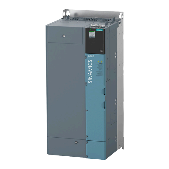
SINAMICS G220
Siemens SINAMICS G220 Manuals
Manuals and User Guides for Siemens SINAMICS G220. We have
1
Siemens SINAMICS G220 manual available for free PDF download: Operating Instructions Manual
Siemens SINAMICS G220 Operating Instructions Manual (834 pages)
Brand:
Siemens
| Category:
Media Converter
| Size: 27.19 MB
Table of Contents
Table of Contents
5
1 Introduction
19
About SINAMICS
19
About this Manual
20
Content
20
Target Group
20
What's New
21
Standard Scope
21
Use of Third-Party Products in this Documentation
21
Websites of Third-Party Companies
22
Product Documentation
23
Service and Support
24
ID Link and Siemens Online Support
24
Spare Parts Services
25
Important Product Information
26
Intended Use
26
Firmware Updates and Constraints
27
Open-Source Software (OSS)
27
Compliance with the General Data Protection Regulation
28
2 Fundamental Safety Instructions
29
General Safety Instructions
29
Equipment Damage Due to Electric Fields or Electrostatic Discharge
36
Warranty and Liability for Application Examples
37
Cybersecurity Information
38
Residual Risks of Power Drive Systems
39
3 Description
41
Converters with Degree of Protection IP20 or UL Open Type
41
Scope of Supply, Converters with Degree of Protection IP20 or UL Open Type
42
Converter in Degree of Protection IP55 or UL Type 12
43
Scope of Delivery, Degree of Protection IP55 or UL Type 12
44
Explanation of the Article Number
45
Optional Components
47
Braking Resistor
47
Function of the Braking Resistor
47
Order Data for Braking Resistor, Degree of Protection IP21
47
Order Data for Braking Resistor, Degree of Protection IP54
48
Memory Card
49
Memory Card Function
49
Memory Card Ordering Data
49
Option Module OM-SMT
50
Option Module OM-Iiot
51
Option Module OM-DQ
51
Ordering Data for Option Modules
52
Expansion Adapter for Option Modules
53
Function of the Expansion Adapter
53
Order Data, Expansion Adapter for Option Modules
53
DRIVE-Cliq Components
53
SINAMICS Smart Adapter
54
Function of the SINAMICS Smart Adapter
54
SINAMICS Smart Adapter Ordering Data
55
SINAMICS SDI Pro 5.5
55
Function of the SINAMICS SDI Pro 5.5
55
Order Data, SINAMICS SDI Pro 5.5
55
Supplementary Optional Components
56
Directives and Standards
57
Motors that Can be Operated
60
Multi-Motor Operation
61
4 Application Planning
63
Protection of Persons from Electromagnetic Fields
63
Protection against the Spread of Fire
65
Protection against Condensation and Conductive Pollution
66
Requirements for the Protective Conductor, Converter in Degree of Protection IP20
67
Requirements for the Protective Conductor, Converter in Degree of Protection IP55
70
Fault Protection for the Motor Circuit
72
Operation on a TN System
73
Operation on a TT System
74
Operation on an IT System
75
Permissible Line System Configuration as a Function of the Installation Altitude
76
Permissible Speed of a Synchronous Motor
77
Star Connection of the Motor or 87 Hz Delta Connection
78
Electromagnetic Compatibility (EMC)
80
Interference Caused by Electromagnetic Fields
80
EMC Category
80
Limit Values for Current Harmonics in the Industrial Supply
81
Current Harmonics
82
EMC Limit Values in South Korea
82
EMC-Compliant Installation
83
EMC Zones in the Control Cabinet
83
Shielding and Potential Equalization Inside the Control Cabinet
83
Potential Equalization between Control Cabinets
84
Electromechanical Components
84
EMC-Compliant Shield Support
86
Electrical Isolation between the Process Control Level and Field Level
87
Shielded Cables, Converter in Degree of Protection IP20
88
Maximum Permissible Signal Cable Lengths, Converter in Degree of Protection IP20
89
Shielded Cables and Ferrites, Converter in Degree of Protection IP55
91
Maximum Permissible Signal Cable Lengths, Converter in Degree of Protection IP55
92
Maximum Permissible Signal Cable Lengths, Option Module OM-SMT
92
Achievable EMC Category and Maximum Motor Cable Length
93
5 Installation
95
Weight, Converter in Degree of Protection IP20
95
Weight, Converter in Degree of Protection IP55
96
Unpacking the Converter
97
Unpacking the Converter, Delivered on Pallets
100
Shield Plates for Converter with IP20 Degree of Protection
102
Mount the Upper Shield Plates
102
Mount the Lower Shield Plates
103
Gland Plate for Connecting Cables, Converter with IP55 Degree of Protection
106
Mount the Gland Plate for Connecting Cables
106
Dimension Drawing of Gland Plate for Connecting Cables
107
Option Modules
111
Maximum Number of Option Modules in the Converter
111
Weight, Option Modules
112
Mounting the Expansion Adapter for Option Modules
112
Mounting Option Module OM-SMT, Converter in Degree of Protection IP20
115
Mounting Option Module OM-SMT, Converter in Degree of Protection IP55
116
Dimension Drawing OM-SMT
119
Mounting Option Module OM-Iiot, Converter in Degree of Protection IP20
119
Mounting Option Module OM-Iiot, Converter in Degree of Protection IP55
120
Dimension Drawing OM-Iiot
123
Mounting Option Module OM-DQ, Converter in Degree of Protection IP20
123
Mounting Option Module OM-DQ, Converter in Degree of Protection IP55
125
Dimension Drawing OM-DQ
127
Supplementary Fan for Option Modules, Converter in Degree of Protection IP20
127
Supplementary Fan for Option Modules, Converter in Degree of Protection IP55
128
6 Mounting
131
Converter
132
Installation Aid
132
Mounting Position
133
Dimensions, Converter in Degree of Protection IP20
134
Minimum Clearances, Converter in Degree of Protection IP20
135
Installation, Converter in Degree of Protection IP20
136
Dimensions, Converter in Degree of Protection IP55
139
Minimum Clearances, Converter in Degree of Protection IP55
140
Installation, Converter in Degree of Protection IP55
141
Braking Resistor
143
Mounting Position
143
Weight, Braking Resistor in Degree of Protection IP21
143
Dimensions, Braking Resistor in Degree of Protection IP21
144
Minimum Clearances, Braking Resistor in Degree of Protection IP21
145
Installation, Braking Resistor in Degree of Protection IP21
146
Weight, Braking Resistor in Degree of Protection IP54
147
Dimensions, Braking Resistor in Degree of Protection IP54
148
Minimum Clearances, Braking Resistor in Degree of Protection IP54
149
Installation, Braking Resistor in Degree of Protection IP54
151
Attaching the Label for the North American Market
152
7 Connecting
153
Line System, Motor and Braking Resistor
153
Connection Overview, Converter in Degree of Protection IP20
153
Connection, Converter in Degree of Protection IP20, 3 AC 200
155
Connection, Converter in Degree of Protection IP20, 3 AC 380
157
Connecting an IP55 Converter
159
Remove and Install Housing Cover, Converter with IP55 Degree of Protection
159
Access to the Power Connections up to Frame Size FSC
161
Connection Overview, Converter in Degree of Protection IP55
162
Connection, Converter in Degree of Protection IP55, 3 AC 200
164
Connection, Converter in Degree of Protection IP55, 3 AC 380
166
Opening the Ground Connection of the Integrated Line Filter, Degree of Protection IP20
168
Opening the Ground Connection of the Integrated Line Filter, Degree of Protection IP55
169
Overcurrent Protection and Fault Current Protection
172
Overcurrent Protection Devices
172
Overcurrent Protection, 3 AC 200
173
Overcurrent Protection, 3 AC 380 V
174
Residual Current Device (RCD)
175
Interfaces for the Controller
178
Overview of Interfaces, Converter in Degree of Protection IP20
178
Overview of Interfaces, Converter in Degree of Protection IP55
179
Requirements Relating to the Fieldbus Cable, Converter with Degree of Protection IP55
180
Connection Example with Internal Supply Voltage
181
Connection Example with External Supply Voltage
181
Control Lines for Terminal Strip
182
Factory Setting of the Terminal Strips
183
Analog Inputs as Additional Digital Inputs
184
Connection Options for the Fail-Safe Digital Inputs
184
Connection Options for the Fail-Safe Digital Output
188
Connecting the Motor Holding Brake
192
Connecting the Temperature Contact of the Braking Resistor
194
Connecting the Auxiliary Contact of the Repair Switch
195
Control Lines for Auxiliary Contacts of the Repair Switch
196
Assignment of the PROFINET Interface
197
Overview of the Interfaces at Option Module OM-SMT
198
Option Module OM-SMT, X230
198
Overview of the Interfaces at Option Module OM-Iiot
201
Option Module OM-Iiot, X128
201
Overview of the Interfaces at Option Module OM-DQ
203
Option Module OM-DQ, X501 and X502
203
8 Commissioning (Hardware)
205
Commissioning after a Long Storage Time
205
Determining the Motor Data
206
9 Software Installation
209
Install Startdrive Commissioning Tool
209
TIA Portal Openness
210
10 Commissioning (Web Server)
211
Introduction
211
Requirements for Commissioning
212
Fundamentals
213
Supported Operating Units
213
Supported Browsers
213
Communication Interfaces
214
Getting Started
215
Calling the Web Server
215
Settings for Brand-New Converters
215
Basic Settings
216
Security Wizard
216
Home Page
218
Making the Product Documentation Available for the Web Server Information System
220
Using the Web Server Information System
221
Reloading
223
Functions and Menus
225
Commissioning
225
Commissioning Sequence
225
Quick Setup
227
Optimization
231
Advanced Setup
231
Testing the Converter Configuration
234
Safety Integrated Commissioning
234
Operator Control and Monitoring
238
Drive Status
238
Inputs/Outputs
239
Diagnostics
241
Messages
241
Diagnostics Buffer
242
Safety Integrated
243
Connection Overview
245
Communication
246
Status Word and Control Word
248
Parameters
249
Parameter List
249
User-Defined Parameter List
252
Signal Interconnections
252
Backup and Restore
254
Overview
254
Save Drive Data to Backup File
256
Scope of the Backup
257
Restoring Drive Data from an Unencrypted Backup File
258
Restoring Drive Data from an Encrypted Backup File
260
Restore Factory Settings
263
Restore Safety Integrated to Factory Settings
264
System
265
Settings
265
Configuring the OM-Iiot Option Module
266
User Management
268
Protection & Security
270
Licenses
271
Firmware Update
273
About Web Server
273
Support
274
Control Panel
275
11 Commissioning (Startdrive)
277
Introduction
277
Basics
278
Communication Interfaces
278
Protected Communication
279
Loading Data from the Drive into the Project
279
Loading Project Data into the Drive
280
Saving Changes in the Project
281
Retentively Saving Changes
282
Using Parameter Lists and User-Defined Lists
283
Device Configuration and Basic Parameterization
285
Overview
285
Simple Basic Parameterization (Offline)
286
Simple Basic Parameterization (Online)
286
Basic Parameterization Together with a SIMATIC Controller
287
Configuring the OM-Iiot Option Module
288
Overview of the Guided Quick Startup
290
Guided Quick Startup
292
Security Settings
293
Differences between Offline and Online Parameterization
294
Extended Parameterization
295
12 Series Commissioning
299
Series Commissioning with Memory Card
300
Series Commissioning Using the Web Server
301
13 Operation and Monitoring with SINAMICS SDI Standard
303
SINAMICS SDI Standard, Converter in Degree of Protection IP20
303
SINAMICS SDI Standard, Converter in Degree of Protection IP55
304
Structure
305
Icons
307
Navigation Bar
307
Footer
307
Status Bar
308
Content Area
309
Functions
311
Adapt Start Page
311
Diagnostics" Menu
311
Displaying Faults and Alarms
311
Operation and Monitoring" Menu
312
Manually Starting and Stopping the Motor
312
Changing the Set Speed of the Motor Manually
313
Change the Direction of Rotation of the Motor Shaft
314
System" Menu
314
Saving the Changes in the Converter
314
Display Interface Information
316
Changing the Converter Date and Time
317
Setting the Display
318
Change Language
318
Support" Menu
319
Scanning the IP Address
319
Retrieving Component Information with a Code Scanner App
320
14 Functions
323
Overview of Converter Functions
323
Brief Description of the Parameters
325
Signal Interconnection
326
PROFINET Communication
328
PROFINET IO Fieldbus
328
Configuring PROFINET IO Operation
328
Connecting the PROFINET Cable to the Converter
328
Configuring Communication Using SIMATIC S7 Control
329
Setting Communication Via PROFINET
329
PROFINET Protocols
330
Media Redundancy
331
Connection-Oriented Communication Protocols
332
Shared Device
333
System Redundancy
334
Telegram Configuration
336
Telegram Structure
336
Telegram 1
336
Telegram 2
337
Telegram 3
337
Telegram 4
338
Telegram 20
338
Telegram 102
339
Telegram 103
339
Telegram 352
340
Telegram 700
341
Telegram 750
341
Telegram 999
342
Control and Status Word 1
345
Control and Status Word 2
353
Message Word
358
NAMUR Message Word
360
Control and Status Word Encoder
360
Safety Info Channel Status Word 1B
362
Actual Position Value of the Encoder
363
Receive Data
365
Send Data
369
Acyclic Profidrive Communication
372
Acyclic Communication
372
Reading Parameter Values
372
Changing Parameter Values
373
Error Value 1 for Read and Change Requests
375
Diagnostics with PROFINET
377
Identification & Maintenance (I&M) Data
379
Profienergy
380
Energy-Saving Mode
380
Energy-Saving Mode 2
380
Setting the Energy-Saving Mode
381
Control Commands for Energy-Saving Mode
382
Status Queries in Energy-Saving Mode
384
Error Values
386
Modbus TCP Communication
387
Modbus TCP Fieldbus
387
Register
387
Application Data Unit
392
Registers Read with Function Code FC 03
392
Registers Write with Function Code FC 06
394
Registers Write with Function Code FC 16
395
Communication Via DS 47
396
Response to an Invalid Write or Read Access Attempt
400
Ethernet/Ip Communication
402
Ethernet/Ip Fieldbus
402
Supported Objects
402
Cyclic Communication
403
Generic I/O Module
403
Assembly Object" Class
404
Acyclic Communication
404
Identity Object" Class
404
Connection Management Object" Class
406
TCP/IP Interfacing Object" Class
407
Ethernet Link Object" Class
408
Siemens Drive Object" Class
411
Siemens Motor Object" Class
413
Parameter Object" Class
414
Communication with Edge Device
416
Communication with the Edge Device
416
Configure Communication with the Converter in the Edge Device
417
Inputs/Outputs
419
Default Settings for Inputs/Outputs
419
I/O Presetting "Conveyor Systems with 4 Fixed Setpoints
419
I/O Presetting "Fieldbus with Data Set Switchover
421
I/O Presetting "Standard I/O with Analog Setpoint
423
Analog Inputs
425
Analog Output
430
Digital Inputs
433
Digital Outputs
436
Setpoint Channel
438
Main Setpoint
438
Motorized Potentiometer as Setpoint Source for the Main Setpoint
440
Fixed Speed Setpoint as Setpoint Source for the Main Setpoint
443
Example for Setting Fixed Speed Setpoint
446
Setpoint Inversion
449
Direction Reversal Without Changing the Setpoint
449
Direction Limiting
451
Minimum Speed
453
Skip Frequency Bands
454
Speed Limitation
456
Ramp-Function Generator
458
Extended Ramp-Function Generator
458
Basic Ramp-Function Generator
459
Jog
464
Closed-Loop Drive Control
467
Motor Reactor, Sine-Wave Filter, and Cable Resistance
467
Standard Drive Control Operating Mode
467
Standard Drive Control
467
Setting of Technological Application in Standard Drive Control
469
Optimized Motor Startup in Standard Drive Control Operating Mode
469
Dynamic Drive Control Operating Mode
475
Differences between Speed Control and Dynamic Drive Control
475
Setting of Technological Application in Dynamic Drive Control
475
U/F Control
495
Voltage Boost
499
Vdc_Min Controller (Vdc_Min Control)
501
Vdc_Max Controller (Voltage Limitation)
502
Slip Compensation
505
Resonance Damping
507
Overcurrent Protection
509
Speed Control
509
Setting of Technological Application for Closed-Loop Speed Control
511
Droop
513
Vdc_Min Controller (Vdc_Min Control)
514
Vdc_Max Controller (Voltage Limitation)
515
Resonance Damping
516
Setting Motor Control for Critical Applications
517
Settings for a Pulling Load
518
Encoderless Speed Control of a Synchronous Reluctance Motor from Standstill
519
Current Setpoint Filter
550
Torque Control
556
Checking the Encoder Signal
558
Moment of Inertia Estimator
559
Efficiency Optimization as a Function of the Motor Operating Point
562
Drive Functions
565
Starting and Stopping the Motor
565
Sequence Control When Switching the Motor on and off
565
Motor Control with On/Reverse Commands
572
Motor Control with Clockwise/Counterclockwise Commands
573
Motor Control with 3 Commands
576
Setting of Device Supply Voltage
579
Units
579
Unit Group and Unit Selection
579
Reference Values
580
Motor Standard
581
Data Sets
582
Switching between Different Drive Configurations
582
Switching between Drive Controls
587
Line Contactor Control
590
DC Braking
592
Armature Short-Circuit Braking
598
Compound Braking
603
Dynamic Braking
605
Motor Holding Brake
607
Automatic Restart
612
Flying Restart - Switching on While Motor Is Running
614
Friction Characteristic
615
Recording a Friction Characteristic
616
Messages/Monitoring Functions
619
Stall Message
619
Blocking Message
619
Speed Deviation Monitoring
620
Load Monitoring for Torque
622
Load Monitoring Failure Detection
623
Load Monitoring
624
Converter Protection by Means of Temperature Monitoring
624
Motor Protection with Temperature Sensor KTY84
629
Motor Protection with Temperature Sensor Pt100
630
14.11.16.10 Motor Protection with Temperature Sensor Pt1000
631
14.11.16.11 Motor Protection with Temperature Switch
632
14.11.16.12 Motor Protection with Temperature Sensor PTC
632
Motor Protection for Synchronous Motors by Means of Temperature Calculation, Model 1
633
Motor Protection for Induction Motors by Means of Temperature Calculation, Model 2
635
Motor Protection for Synchronous Motors by Means of Temperature Calculation, Model 3
638
Setting Motor Overload Protection According to UL 61800-5-1
640
Safety Integrated
656
Safety Integrated Functions
658
PFH Values
659
EMERGENCY off and EMERGENCY STOP
659
Stop Functions
661
Safe Torque off (STO)
661
Safe Stop 1 (SS1) - Overview
663
Safe Stop 1 with Time Control (SS1-T)
664
Safe Stop 1 with Acceleration Monitoring (SS1-A)
666
Safe Stop 1 with Braking Ramp Monitoring (SS1-R)
668
Setting the SS1 Delay Time
671
Motion Monitoring
671
Safely-Limited Speed (SLS)
671
SLS with Variable Speed Limit Value
674
Limitation of the Speed Setpoint for SLS
674
Safe Speed Monitor (SSM)
675
Safe Direction (SDI)
678
Limitation of the Speed Setpoint for SDI
679
Safe Motor Temperature (SMT)
680
Selection of the Safety Integrated Functions
682
Safe Actual Value Acquisition/Mechanical System
683
Control
685
Control Via Profisafe
685
Telegram 30
687
Telegram 902
687
Safety Control Word 1 and Safety Status Word 1
688
Safety Control Word 2 and Safety Status Word 2
689
Transferring the F-DI Status Via Profisafe
694
Control Via Profisafe and EMERGENCY STOP Via Terminals
694
Control Via Terminals
695
Discrepancy Time
695
Input Filter
697
Self-Test of the Fail-Safe Digital Input (F-DI)
697
F-DO Configuration
704
Self-Test of the Fail-Safe Digital Output
704
Status and Diagnostics of the Safety Integrated Functions
708
Responses to Safety Messages
711
Stop Responses
711
Priority of Stop Responses and Stop Functions
711
Fail-Safe Acknowledgment of Safety Messages
712
Functional Safety
713
Machinery Directive
714
Technology Functions
715
PID Technology Controller
715
Manually Setting the Controller Parameters of the PID Technology Controller
723
Bypass
724
Functions that Require Licensing
730
Using Functions that Require a License
730
System Responses to Under-Licensing (Ramp-Up)
731
System Responses to Under-Licensing (Operation)
731
Creating and Downloading the License File
732
Downloading the License File at a Later Time
733
Transferring the License File to the Converter and Activating It
733
Restoring Licensing after the Memory Card Is Removed
734
Loading Certificates of License (Ecol) into the File Directory of the Operating Unit
735
15 System Messages
737
Leds
737
Leds on the Converter
737
Explanation of Icons
738
Led Lnk
738
LED RDY and LED COM
739
LED RDY of the Option Modules
741
LED COM of Option Module OM-Iiot
742
Identification & Maintenance (I&M) Data
743
Date and Time
744
Faults and Alarms
745
Alarms
746
Alarm Buffer
747
Faults
750
Fault Buffer
751
Safety Message Buffer
755
Deleting a Safety Message Buffer
758
16 Corrective Maintenance
761
Replacing a Converter
761
Replacing the Converter Without Memory Card
763
Restoring the Drive Data Via the Web Server
763
Restoring Data from an Unencrypted Backup File
764
Restoring Data from an Encrypted Backup File
766
Restore Factory Settings
769
Firmware Update Via Memory Card
770
Firmware Update of Option Module OM-Iiot
772
Deleting the Public Key of Option Module OM-Iiot
776
Full Reset of All Device Settings
779
Safety Integrated Acceptance Test after Component Replacement
781
Device Replacement Without Removable Data Storage Medium Via PROFINET
782
Spare Parts
783
Spare Parts Compatibility
784
Replacing Fans
785
Replace Fan Unit, Converter with IP20 Degree of Protection
785
Replace Fan Unit, Converter with IP55 Degree of Protection, Frame Sizes FSB-FSC
789
Replace Fan Unit, Converter with IP55 Degree of Protection, Frame Sizes FSD1-FSE
791
Remove and Install Housing Cover, Converter with IP55 Degree of Protection
793
Replace Interior Fan, Converter with IP55 Degree of Protection, Frame Sizes FSB-FSC
795
Replace Interior Fan, Converter with IP55 Degree of Protection, Frame Sizes FSD1-FSE
797
Device Disposal
800
17 Technical Data
801
General Technical Specifications
801
Environmental Conditions
802
Mechanical Environmental Conditions
802
Chemical Environmental Conditions
802
Biological Environmental Conditions
803
Climatic Conditions
803
Power, Input Current, Output Current
804
3 Ac
804
415 V 3 Ac / 440 V
806
Overload Capability of the Converter
807
Low Overload" and "High Overload" Duty Cycles
809
Duty Cycle for Synchronous Reluctance Motors
809
Braking Resistor Connections
810
Permissible Output Current Depending on the Installation Altitude and Ambient Temperature, IP20
811
Permissible Output Current Depending on the Installation Altitude and Ambient Temperature, IP55
813
17.6 Permissible Motor Cable Length as a Function of the Pulse Frequency
814
Current Derating Depending on the Pulse Frequency
815
Permitted Output Current at Low Speeds
816
Power Loss
817
Ac 200
817
Ac 380 V
817
Ac 200
818
Ac 380 V
819
Data Regarding the Power Loss in Partial Load Operation
819
Inputs and Outputs
820
Safety Integrated Functions
822
Service Life
822
Monitoring Cycle and Profisafe Cycle
822
Response Times - Independent of the Control Type
822
Response Times When Controlling Via Profisafe
823
Response Times When Controlling Via Terminals
824
SINAMICS SDI Standard
826
Option Modules
827
Option Module OM-SMT
827
Option Module OM-Iiot
828
Option Module OM-DQ
828
Climatic Conditions
829
Braking Resistor
830
Electrical Data for Braking Resistor, Degree of Protection IP21
830
Electrical Data for Braking Resistor, Degree of Protection IP54
831
Advertisement
Advertisement
Related Products
Siemens SINAMICS G150
Siemens SINAMICS G130
Siemens SINAMICS G12
Siemens SINAMICS G120C DP
Siemens SINAMICS G120C PN
Siemens SINAMICS G120XA
Siemens SINAMICS G120X
Siemens SINAMICS G110D 6SL3511-0PE21-5AM0
Siemens SINAMICS G110D 6SL3511-0PE27-5AM0
Siemens SINAMICS G110D 6SL3511-0PE23-0AM0
Siemens Categories
Industrial Equipment
Controller
Control Unit
Oven
Washer
More Siemens Manuals
Login
Sign In
OR
Sign in with Facebook
Sign in with Google
Upload manual
Upload from disk
Upload from URL