Sign In
Upload
Manuals
Brands
Siemens Manuals
Control Unit
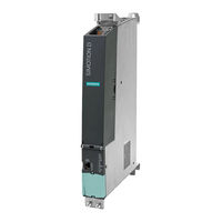
SIMOTION D425
Siemens SIMOTION D425 Manuals
Manuals and User Guides for Siemens SIMOTION D425. We have
7
Siemens SIMOTION D425 manuals available for free PDF download: Manual, Equipment Manual
Siemens SIMOTION D425 Manual (150 pages)
Brand:
Siemens
| Category:
Control Unit
| Size: 7.9 MB
Table of Contents
Preface
3
Table of Contents
7
1 Description
11
System Overview
11
System Components
16
I/O Integration
21
Representation of SIMOTION D425-2 DP and D435-2 DP
22
Representation of SIMOTION D425-2 DP/PN and D435-2 DP/PN
24
Representation of SIMOTION D445-2 DP/PN and D455-2 DP/PN
26
Type Plates
28
Safety Information
30
Compactflash Card
31
Usage and Function of the Compactflash Card
31
Compactflash Card
33
Data Matrix Code on Compactflash Card
35
2 Operator Control (Hardware)
37
Overview of Operator Control and Display Elements
37
Operator Controls
39
Service and Operating Mode Switch
39
DIAG Button
43
RESET Button
43
7-Segment and LED Displays
44
3 Interfaces
47
Interface Overview
47
DRIVE-Cliq Interfaces
49
Ethernet Interfaces
51
PROFINET IO Interface (Only for SIMOTION D4X5-2 DP/PN)
55
Digital I/Os
58
Properties
58
Using the Digital Inputs/Outputs
62
Power Supply
64
PROFIBUS DP Interfaces
66
Slot for Compactflash Card
69
Measuring Sockets
70
USB Interfaces
71
4 Technical Data of the D4X5-2
73
Shipping and Storage Conditions
73
Mechanical and Climatic Ambient Conditions
75
Dimensions and Weights
77
Power Supply
78
Interfaces and Performance Features
80
Compactflash Card
85
Clock
85
Input and Output Circuit
86
5 Dimension Drawings
87
D425-2 and D435-2 Dimension Drawing
87
D445-2 DP/PN and D455-2 DP/PN Dimension Drawing
88
CAD Data, Dimension Drawings, and Circuit-Diagram Macros
89
6 Supplementary System Components
91
Connection Options Overview
91
Fan/Battery Module
93
Cooling the SIMOTION D4X5-2 and Backing up the Real-Time Clock
93
Installing the Fan/Battery Module
95
Replace Battery in the Fan/Battery Module
96
TB30 Terminal Board
99
Description
99
Safety Information for the TB30
99
Interfaces
100
Overview
100
Connection Diagram
101
Power Supply of Digital Outputs
102
Digital I/Os
103
Analog Inputs and Outputs
104
Working with Analog Inputs
105
Commissioning
105
Technical Specifications
105
CBE30-2 Ethernet Communication Board
107
Overview
107
Type Plate
108
Safety Information
109
Interface Description
109
LED Displays
111
Dimension Drawing
112
Commissioning
112
Technical Data
113
CX32-2 Controller Extension
114
Overview of CX32-2
114
Interfaces
116
Overview of Interfaces
116
List of Interfaces
117
DRIVE-Cliq Interface
118
Digital I/Os (X122)
118
Power Supply
122
Measuring Sockets
123
Displays of the Leds
123
Cause and Rectification of Faults
123
RESET Button
124
Commissioning
124
Technical Data of the CX32-2
124
Terminal Module TM31
128
Terminal Module TM41
129
Terminal Module TM54F
130
TM15 and TM17 High Feature Terminal Modules
131
CUA31/CUA32 Control Unit Adapter
132
DMC20 DRIVE-Cliq Hub
133
7 Spare Parts/Accessories
135
Available Spare Parts and Accessories
135
Standards and Approvals
137
General Rules
137
SIMOTION D4X5-2 Device-Specific Notes
139
Safety of Electronic Controllers
140
ESD Guidelines
143
ESD Definition
143
Electrostatic Charging of Individuals
144
Basic Measures for Protection against Discharge of Static Electricity
145
Index
147
Advertisement
Siemens SIMOTION D425 Manual (126 pages)
Brand:
Siemens
| Category:
Control Unit
| Size: 4.95 MB
Table of Contents
Preface
3
Table of Contents
7
1 Safety Instructions
11
Fundamental Safety Instructions
11
General Safety Instructions
11
Safety Instructions for Electromagnetic Fields (EMF)
14
Handling Electrostatic Sensitive Devices (ESD)
14
Industrial Security
15
Residual Risks of Power Drive Systems
16
Specific Safety Information for SIMOTION D4X5
18
2 Description
19
System Overview
19
System Components
23
I/O Integration
27
Representation of SIMOTION D425 and SIMOTION D435
28
Representation of SIMOTION D445
30
SIMOTION D445-1 Image
32
Nameplates
33
Compactflash Card
35
Usage and Function of the Compactflash Card
35
Compactflash Card
36
Data Matrix Code on CF Card
38
3 Operator Control (Hardware)
41
Overview of Operator Control and Display Elements
41
Operator Control Elements
43
Service and Operating Mode Switch
43
RESET Button
46
7-Segment Display and LED Display
46
4 Interfaces
49
Interface Overview
49
DRIVE-Cliq Interfaces
50
Ethernet Interfaces
52
Digital Inputs/Digital Outputs
54
Features
54
Using the Digital Inputs/Outputs
57
Power Supply
58
PROFIBUS DP Interfaces
60
Slot for Compactflash Card
62
Measuring Sockets
62
USB Interfaces
63
Option Slot
63
5 Technical Data
65
Technical Data D4X5
65
Clock
72
D4X5 Power Supply
73
Specifications for Protection Class and Degree of Protection
74
Input and Output Circuit
75
6 Dimension Drawings
77
Dimension Drawing of D425 and D435
77
Dimension Drawing of D445
78
D445-1 Dimension Drawing
79
CAD Data, Dimension Drawings, and Circuit-Diagram Macros
80
7 Supplementary System Components
81
Supplemental System Components
81
Fan/Battery Module
83
Cooling SIMOTION D4X5 and Buffering Data
83
Installing the Fan/Battery Module
85
Replace Battery in the Fan/Battery Module
86
TB30 Terminal Board
88
Description
88
Safety Information for the TB30
88
Interfaces
89
Overview
89
Connection Diagram
90
Power Supply of Digital Outputs
90
Digital Inputs/Outputs
91
Analog Inputs and Outputs
93
Working with Analog Inputs
94
Commissioning
94
Technical Specifications
94
Controller Extension CX32
94
Overview of CX32
94
Interfaces
96
List of Interfaces
97
DRIVE-Cliq Interface
98
Digital Inputs/Outputs (X122)
98
Power Supply
101
Measuring Sockets
102
Displays of the Leds
103
RESET Button
103
Commissioning
103
Technical Data
104
CBE30 Communication Board Ethernet
107
CBE30 Communication Board
107
Nameplates
108
Safety Information
109
Interface Description
110
Ethernet Interfaces
110
LED Displays
111
Dimension Drawing
112
Commissioning
112
Technical Data
113
Terminal Module TM31
113
Terminal Module TM41
114
Terminal Module TM54F
115
Terminal Modules TM15 and TM17 High Feature
116
CUA31/CUA32 Control Unit Adapter
117
DMC20 DRIVE-Cliq Hub
118
8 Available Spare Parts and Accessories
119
Standards and Approvals
121
General Rules
121
SIMOTION D4X5 Device-Specific Notes
122
ESD Guidelines
123
ESD Definition
123
Electrostatic Charging of Individuals
123
Basic Measures for Protection against Discharge of Static Electricity
124
Index
125
Siemens SIMOTION D425 Manual (130 pages)
Brand:
Siemens
| Category:
Control Unit
| Size: 4.8 MB
Table of Contents
Preface
3
Table of Contents
7
1 Description
11
System Overview
11
System Components
15
I/O Integration
20
Representation of SIMOTION D425 and SIMOTION D435
21
Representation of SIMOTION D445
22
SIMOTION D445-1 Image
23
Nameplates
25
Safety Notes
27
Compactflash Card
28
Usage and Function of the Compactflash Card
28
Compactflash Card
30
Data Matrix Code on CF Card
32
2 Operator Control (Hardware)
33
Overview of Operator Control and Display Elements
33
Operator Control Elements
35
Service and Operating Mode Switch
35
RESET Button
39
7-Segment Display and LED Display
39
3 Interfaces
41
Interface Overview
41
DRIVE-Cliq Interfaces
42
Ethernet Interfaces
44
Digital Inputs/Digital Outputs
46
Features
46
Using the Digital Inputs/Outputs
49
Power Supply
51
PROFIBUS DP Interfaces
52
Slot for Compactflash Card
55
Measuring Sockets
55
USB Interfaces
56
Option Slot
56
4 Technical Data
57
Technical Data D4X5
57
Clock
65
D4X5 Power Supply
66
Specifications for Protection Class and Degree of Protection
67
Input and Output Circuit
68
5 Dimension Drawings
69
Dimension Drawing of D425 and D435
69
Dimension Drawing of D445
70
D445-1 Dimension Drawing
71
CAD Data, Dimension Drawings, and Circuit-Diagram Macros
72
6 Supplementary System Components
73
Supplemental System Components
73
Fan/Battery Module
74
Cooling SIMOTION D4X5 and Buffering Data
74
Installing the Fan/Battery Module
77
Replace Battery in the Fan/Battery Module
78
TB30 Terminal Board
80
Description
80
Safety Information for the TB30
80
Interfaces
81
Overview
81
Connection Diagram
82
Power Supply of Digital Outputs
83
Digital Inputs/Outputs
84
Analog Inputs and Outputs
86
Working with Analog Inputs
87
Commissioning
87
Technical Specifications
87
Controller Extension CX32
88
Overview of CX32
88
Interfaces
90
List of Interfaces
91
DRIVE-Cliq Interface
92
Digital Inputs/Outputs (X122)
92
Power Supply
96
Measuring Sockets
97
Displays of the Leds
97
RESET Button
97
Commissioning
98
Technical Data
98
CBE30 Communication Board Ethernet
102
CBE30 Communication Board
102
Nameplates
103
Safety Information
104
Interface Description
105
Ethernet Interfaces
105
LED Displays
106
Dimension Drawing
107
Commissioning
108
Technical Data
108
Terminal Module TM31
109
Terminal Module TM41
110
Terminal Module TM54F
111
Terminal Modules TM15 and TM17 High Feature
112
CUA31/CUA32 Control Unit Adapter
113
DMC20 DRIVE-Cliq Hub
114
7 Available Spare Parts and Accessories
115
Standards and Approvals
117
General Rules
117
SIMOTION D4X5 Device-Specific Notes
119
Safety of Electronic Controllers
120
ESD Guidelines
123
ESD Definition
123
Electrostatic Charging of Individuals
124
Basic Measures for Protection against Discharge of Static Electricity
125
Index
127
Advertisement
Siemens SIMOTION D425 Manual (126 pages)
Brand:
Siemens
| Category:
Control Unit
| Size: 6.16 MB
Table of Contents
Preface
3
Table of Contents
7
Description
11
System Overview
11
System Components
16
I/O Integration
20
View of SIMOTION D445-2 DP/PN and D455-2 DP/PN
22
Nameplates
23
Safety Notes
25
Compactflash Card
26
Usage and Function of the Compactflash Card
26
Compactflash Card
28
Data Matrix Code on CF Card
29
Operation (Hardware)
31
Overview of Operator Control and Display Elements
31
Operator Controls
32
Service and Operating Mode Switch
32
DIAG Button
36
RESET Button
36
7-Segment and LED Displays
37
Interfaces
39
Interface Overview
39
DRIVE-Cliq Interfaces
40
Ethernet Interfaces
42
PROFINET IO Interface
45
Digital Inputs/Outputs
49
Features
49
Using the Digital Inputs/Outputs
53
Power Supply
55
PROFIBUS DP Interfaces
56
Slot for Compactflash Card
59
Measuring Sockets
59
USB Interfaces
61
Technical Data of the D4X5-2
63
Shipping and Storage Conditions
63
Mechanical and Climatic Ambient Conditions
64
Dimensions and Weights
66
Power Supply
67
Interfaces and Performance Features
68
Compactflash Card
72
Clock
72
Input and Output Circuit
73
Dimension Drawings
75
Dimension Drawing of D445-2 DP/PN and D455-2 DP/PN
75
CAD Data, Dimension Drawings, and Circuit-Diagram Macros
76
Supplementary System Components
77
Supplemental System Components
77
Fan/Battery Module
79
Cooling the SIMOTION D4X5-2 and Backing up the Real-Time Clock
79
Installing the Fan/Battery Module
80
Replace Battery in the Fan/Battery Module
82
TB30 Terminal Board
85
Description
85
Safety Information for the TB30
85
Interfaces
86
Overview
86
Connection Diagram
87
Power Supply of Digital Outputs
88
Digital Inputs/Outputs
89
Analog Inputs and Outputs
90
Working with Analog Inputs
91
Commissioning
91
Technical Specifications
91
CX32-2 Controller Extension
92
Overview of CX32-2
92
Interfaces
94
Overview of Interfaces
94
List of Interfaces
95
DRIVE-Cliq Interface
96
Digital Inputs/Outputs (X122)
96
Power Supply
100
Measuring Sockets
101
Displays of the Leds
101
Cause and Rectification of Faults
102
RESET Button
102
Commissioning
102
Technical Data of the CX32-2
102
Terminal Module TM31
106
Terminal Module TM41
107
SIMOTION D4X5-2
107
Terminal Module TM54F
107
Terminal Modules TM15 and TM17 High Feature
109
CUA31/CUA32 Control Unit Adapter
110
DMC20 DRIVE-Cliq Hub
110
Available Spare Parts and Accessories
113
Standards and Approvals
115
General Rules
115
Safety of Electronic Controllers
117
ESD Guidelines
119
ESD Definition
119
Electrostatic Charging of Individuals
120
Basic Measures for Protection against Discharge of Static Electricity
121
Index
123
Siemens SIMOTION D425 Equipment Manual (80 pages)
Brand:
Siemens
| Category:
Control Unit
| Size: 2.6 MB
Table of Contents
Table of Contents
7
1 Introduction
11
Hardware Components
11
Product Description of D4Xx
12
Software Components
12
Product Variants
13
System Components
15
Table 1-2 Central Components
15
Table 1-3 System Components
15
Table 1-4 Distributed I/O Systems
16
Table 1-5 Optional Components for the Control Unit
16
Table 1-6 Additional Components that Can be Connected to the Control Unit
17
2 Description
19
Safety Notes
19
D435 and D425
20
D445
21
Clock
22
Table 2-1 Clock Features
22
Power Supply of D425 and D435
23
Power Supply of D445
24
3 Operator Control (Hardware)
25
Operator Control and Display Elements
25
LED Displays
25
Table 3-1 Meaning of LED States
26
Nameplates
29
Interfaces
30
Mode Selector
31
Reset Button
32
Table 3-3 Mode Selector Settings
32
Simotion Cf
33
Properties of the Compactflash Card
33
Compactflash Slot
34
Changing the Compact Flash Card
35
Writing to Compactflash Card
36
Memory Concept
37
Memory Concept of SIMOTION D
37
Persistent Data (Non-Volatile Data)
38
Monitoring Persistent Data (Non-Volatile Data)
38
Power off Behavior
40
4 Interfaces
41
Interface Overview
41
Table 4-1 Overview of Available External Interfaces
41
DRIVE Cliq Interfaces
42
Use of DRIVE Cliq Interface
43
Ethernet Interfaces
44
Ethernet Interfaces X120 and X130
44
Use of Ethernet Interfaces
45
Digital Inputs/Outputs
46
X122 and X132 Digital Inputs
46
Pin Assignment for Interfaces X122 and X132
48
Technical Data for X122 and X132
49
Use of X122 and X123 Interfaces
50
Power Supply
51
Power Supply X124
51
PROFIBUS-DP Interfaces
52
PROFIBUS-DP Interfaces X126 and X136
52
Table 4-14 PROFIBUS-DP X126 Interface
53
Table 4-15 PROFIBUS-DP X136 Interface
53
Use of PROFIBUS-DP Interfaces
54
Compactflash Slot
55
Measuring Sockets
55
Measuring Sockets X131 - X134
55
5 Technical Data
57
Technical Data for D435 and D425
57
Table 5-1 Memories for User Data and Their Memory Size
57
Table 5-2 Electrical Connection Values
57
Table 5-3 Dimension and Weight of D435 and D425
57
Technical Data for D445
58
Table 5-4 Environmental Requirements
58
Table 5-5 Memories for User Data and Their Memory Size
58
6 Dimension Drawings
61
Dimension Drawing of D435 and D425
61
Dimension Drawing of D445
62
7 Spare Parts/Accessories
63
Fan/Battery Module
63
Cooling the SIMOTION D4Xx
63
Fan/Battery Module Assembly
64
Battery Replacement in the Fan/Battery Module
65
Supplemental System Components
66
Terminal Board TB30
67
Terminal Module TM31
67
Terminal Module TM41
68
Terminal Modules TM15 and TM17 High Feature
69
CX32 Module
70
Appendices
71
Standards
71
Information on Insulation Tests, Safety Class, and Degree of Protection
71
A.1 Standards
71
Rated Voltage for Operation of the D4Xx
72
Safety of Electronic Controllers
73
EC Declaration of Conformity
74
A.5 EC Declaration of Conformity
74
ESD Guidelines
75
Electrostatically Sensitive Modules
75
Electrostatic Accumulation on Individuals
76
Basic Measures for Protection against Discharge of Static Electricity
77
Index
79
Siemens SIMOTION D425 Manual (76 pages)
Brand:
Siemens
| Category:
Industrial Electrical
| Size: 2.33 MB
Table of Contents
Preface
3
Table of Contents
7
1 Description
11
System Overview
11
Table 1-1 Product Variants
12
System Components
14
Table 1-2 Central Components
14
Table 1-3 Components on PROFIBUS DP
14
Table 1-4 Components on the Ethernet
15
Table 1-5 Components on the PROFINET
16
Table 1-6 Components on DRIVE-Cliq
17
Table 1-7 Optional Components for the Control Unit
17
Approved Components for SIMOTION D
18
Representation of SIMOTION D425 and SIMOTION D435
19
Representation of SIMOTION D445
20
Nameplates
21
Safety Notes
23
2 Operator Control (Hardware)
25
Overview of Operator Control and Display Elements
25
Operator Control Elements
26
Mode Selector
26
Table 2-1 Mode Selector Position
27
Table 2-2 Mode Selector Settings
27
SIMOTION Compact Flash Card
28
RESET Button
29
LED Displays
30
Table 2-3 Error and Status Displays
31
3 Interfaces
33
Interface Overview
33
Table 3-1 Overview of Available External Interfaces
33
Table 3-2 Overview of Interfaces that Cannot be Used for SIMOTION D
33
DRIVE-Cliq Interfaces
34
Table 3-3 X100 - X103 (SIMOTION D425, D435) or X100 - X105 (SIMOTION D445)
34
Table 3-4 DRIVE-Cliq Interface (X100 - X103 or X100 - X105)
35
Ethernet Interfaces X120 and X130
36
Table 3-5 X120 and X130
37
Table 3-6 Ethernet Interfaces (X120 and X130)
37
Digital Inputs/Digital Outputs
38
Digital Inputs/Digital Outputs X122, X132
38
Table 3-7 Interfaces X122 and X132
38
Table 3-8 Digital Inputs/Digital Outputs X122
40
Table 3-9 Digital Inputs/Digital Outputs X132
40
Technical Data for X122 and X132
41
Table 3-10 Technical Data for Digital Inputs X122/X132
41
Table 3-11 Technical Data of Digital Inputs/Digital Outputs X122/X132
41
Use of X122 and X123 Interfaces
42
Power Supply X124
44
Table 3-12 Interface X124
44
Table 3-13 Power Supply X124
44
PROFIBUS DP Interfaces X126 and X136
45
Table 3-14 Interfaces X126 and X136
45
Table 3-15 PROFIBUS DP Interface X126
45
Table 3-16 PROFIBUS DP Interface X136
45
Compactflash Slot
47
Measuring Sockets X131 - X134
48
4 Technical Data
49
Technical Data for D435 and D425
49
Table 4-1 Memory for System Data and the Memory Size
49
Table 4-2 Electrical Connection Values
49
Table 4-3 Dimension and Weight of D435 and D425
49
Technical Data for D445
50
Table 4-4 Environmental Requirements
50
Table 4-5 Memory for System Data and the Memory Size
50
Table 4-6 Electrical Connection Values
51
Table 4-7 Dimensions and Weight of a D445
51
Table 4-8 Environmental Requirements
51
Clock
52
Table 4-9 Clock Features
52
D4X5 Power Supply
53
Rated Voltage for Operation of the D4X5
53
Information on Insulation Tests, Safety Class, and Degree of Protection
54
5 Dimension Drawings
55
Dimension Drawing of D435 and D425
55
Dimension Drawing of D445
56
6 Spare Parts/Accessories
57
Supplemental System Components
57
Fan/Battery Module
58
Cooling the SIMOTION D4X5
58
Fan/Battery Module Assembly
59
Replace Battery in the Fan/Battery Module
60
Terminal Board TB30
61
CBE30 Communication Board
61
Terminal Module TM31
62
Terminal Module TM41
63
Terminal Module TM54F
64
Terminal Modules TM15 and TM17 High Feature
65
DMC20 DRIVE-Cliq Hub
66
CX32 Module
66
List of Available Spare Parts and Accessories
67
Standards and Approvals
69
General Rules
69
Safety of Electronic Controllers
70
Electromagnetic Compatibility
71
ESD Guidelines
73
ESD Definition
73
Electrostatic Charging of Individuals
74
Basic Measures for Protection against Discharge of Static Electricity
74
Index
75
Siemens SIMOTION D425 Manual (90 pages)
Brand:
Siemens
| Category:
Control Unit
| Size: 3.55 MB
Table of Contents
Preface
3
Table of Contents
7
1 Description
9
System Overview
9
System Components
13
I/O Integration
17
Representation of SIMOTION D425 and SIMOTION D435
18
Representation of SIMOTION D445
19
SIMOTION D445-1 Image
21
Nameplates
22
Safety Notes
24
Compactflash Card
25
Usage and Function of the Compactflash Card
25
Compactflash Card
27
2 Operator Control (Hardware)
29
Overview of Operator Control and Display Elements
29
Operator Control Elements
31
Service and Operating Mode Switch
31
RESET Button
33
LED Displays
34
3 Interfaces
37
Interface Overview
37
DRIVE-Cliq Interfaces
38
Ethernet Interfaces
39
Digital Inputs/Digital Outputs
42
Features
42
Using the Digital Inputs/Outputs
45
Power Supply
46
PROFIBUS DP Interfaces
47
Slot for Compactflash Card
50
Measuring Sockets
50
USB Interfaces
51
Option Slot
51
4 Technical Data
53
Technical Data D4X5
53
Clock
58
D4X5 Power Supply
59
Information on Insulation Tests, Safety Class, and Degree of Protection
60
Input and Output Circuit
61
5 Dimension Drawings
63
Dimension Drawing of D425 and D435
63
Dimension Drawing of D445
64
D445-1 Dimension Drawing
65
CAD Data, Dimension Drawings, and Circuit-Diagram Macros
66
6 Spare Parts/Accessories
67
Supplemental System Components
67
Fan/Battery Module
68
Cooling SIMOTION D4X5 and Buffering Data
68
Installing the Fan/Battery Module
70
Replace Battery in the Fan/Battery Module
71
Terminal Board TB30
72
CBE30 Communication Board
73
Terminal Module TM31
74
Terminal Module TM41
75
Terminal Module TM54F
75
Terminal Modules TM15 and TM17 High Feature
76
CUA31/CUA32 Control Unit Adapter
77
DMC20 DRIVE-Cliq Hub
78
Controller Extension CX32
79
Available Spare Parts and Accessories
81
Standards and Approvals
83
General Rules
83
A.1 General Rules
83
Safety of Electronic Controllers
84
Electromagnetic Compatibility
86
A.3 Electromagnetic Compatibility
86
ESD Guidelines
87
ESD Definition
87
Electrostatic Charging of Individuals
87
B.1 ESD Definition
87
Basic Measures for Protection against Discharge of Static Electricity
88
Index
89
Advertisement
Related Products
Siemens SIMOTION D425-2
Siemens SIMOTION D425-2 DP
Siemens SIMOTION D435-2
Siemens SIMOTION D445-2
Siemens SIMOTION D455-2
Siemens SIMOTION D410 DP
Siemens SIMOTION D410 DN
Siemens SIMOTION D445-1
Siemens SIMOTION D4 5 Series
Siemens SIMOTION D4x5-2
Siemens Categories
Industrial Equipment
Controller
Control Unit
Oven
Washer
More Siemens Manuals
Login
Sign In
OR
Sign in with Facebook
Sign in with Google
Upload manual
Upload from disk
Upload from URL