Sign In
Upload
Manuals
Brands
Siemens Manuals
Control Unit
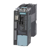
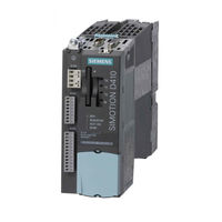
SIMOTION D410 DP
User Manuals: Siemens SIMOTION D410 DP Control Unit
Manuals and User Guides for Siemens SIMOTION D410 DP Control Unit. We have
5
Siemens SIMOTION D410 DP Control Unit manuals available for free PDF download: Commissioning Manual, Manual
Siemens SIMOTION D410 DP Commissioning Manual (230 pages)
Brand:
Siemens
| Category:
Controller
| Size: 4.43 MB
Table of Contents
Preface
3
Table of Contents
7
1 Description
13
System Overview
13
System Components
15
SIMOTION D410 DP Display
21
SIMOTION D410 PN Display
24
The Compactflash Card
26
Licensing
27
Safety Information
28
2 Commissioning (Hardware)
29
Prerequisites for Commissioning
29
Inserting the Compact Flash Card
30
Switching on the Power Supply
31
RESET Button
32
User Memory Concept
33
SIMOTION D410 Memory Model
33
Properties of the User Memories
34
Operator Actions and Their Impact on User Memory
37
3 Parameter Assignment / Addressing
45
Software Requirements
45
Creating a Project and Configuring the Communication
45
Creating a SIMOTION Project and Inserting a SIMOTION D410
45
Configuring the Properties of the PROFINET Interface
48
Configuring the PROFIBUS PG/PC Interface (Only for D410 DP)
49
Configuring the Ethernet PG/PC Interface (Only for D410 PN)
50
Representation in HW Config
52
Configuring the PROFIBUS DP Interface (Only D410 DP)
53
General Information about PROFIBUS DP Communication
53
Assignment of the PROFIBUS Addresses in HW Config
54
Operating SIMOTION D410 on PROFIBUS DP
55
Creating a New PROFIBUS DP Subnet
55
Setting the DP Cycle and System Cycle Clocks
56
Rules for SIMOTION D410 DP
57
Operating the PROFIBUS Interface (X21) as an MPI Interface
58
Configuring PROFINET (Only for D410 PN)
59
General Information about PROFINET Communication
59
Operating SIMOTION D410 PN on PROFINET
60
Setting the Send Cycles and System Clocks
63
Rules for SIMOTION D410 PN
64
4 Commissioning (Software)
67
Overview of Commissioning
67
Symbolic Assignment / Adaptation
67
Procedure When Commissioning
71
Important Functions for the Project Handling During Commissioning
72
Configuring the System in Offline Mode
73
Overview
73
Accessing the Drive Wizard
74
Configuring the Components
74
Downloading the Project to the Target System
81
Loading a Project Created Offline to the Compactflash Card
82
Downloading the Project Incl. Sources and Additional Data
83
Archiving a Project on the Compactflash Card (Zip File)
84
Performing an Online Configuration
85
Overview
85
Establishing the Online Connection
86
Starting Automatic Configuration
86
Editing SINAMICS Components
89
Download the Project to SIMOTION D410
90
Additional Information on Configuring the SINAMICS Integrated
91
Setting DP Slave Properties
91
Using Vector Drives
93
Set Time of Day
94
SINAMICS Diagnostic Buffer
97
Acyclic Communication with the Drive
98
Control Properties and Performance Features
100
Current Controller Cycle Clocks <> 125 Μs / Use of Output Cams and Measuring Inputs
100
Testing the Configured Drive Using the Drive Control Panel
101
Creating and Testing an Axis
103
Overview of SIMOTION Engineering
103
Creating an Axis with the Axis Wizard
104
Testing an Axis with the Axis Control Panel
111
Setting up Addresses and Message Frames
114
Setting up Communication for Symbolic Assignment
114
Message Frame Configuration
115
Integrating Additional Encoders (Optional)
118
General Information
118
Configuring Additional Encoders on the Drive
119
Connecting Additional Encoders Via PROFIBUS/PROFINET
120
Symbolic Assignment of I/O Variables (Profidrive Message Frame / Drive Parameters)
121
Assignment to the Profidrive Message Frame of the to Axis
121
Assignment to Drive Parameters
121
Configuring Drive-Related I/Os (with Symbolic Assignment)
125
Configuring I/O Terminals
127
Configuration of SIMOTION D410 I/Os (Terminal X121)
128
Configuration of Cu3Xx/Tb30/Tmxx I/Os
129
Configuring TMC I/O Terminals
129
Configuring Technology Objects and I/O Variables
129
Configuring Global Measuring Inputs
129
Configuring Local Measuring Inputs
131
Configuring Output Cams / Cam Tracks
132
Configuration of I/Os (Variables / to Axis)
134
Creating a DMC20/DME20
135
Hub Properties
136
Creating a DRIVE-Cliq Hub
136
Creating and Programming TM41
137
Overview
137
Configuring TM41 at SINAMICS Integrated
138
Optimizing the Drive and Controller
138
Overview of Automatic Controller Setting
138
Automatic Speed Controller Setting
139
Automatic Position Controller Setting
140
Measuring Functions, Trace, and Function Generator
142
Manual Speed Controller Optimization
143
Downloading and Saving SIMOTION User Data
148
Deleting Data
150
Overview of Data Deletion
150
Resetting the Memory of SIMOTION D410
150
Deleting User Data from the Compactflash Card
153
Restoring the Default Settings of SINAMICS Integrated
153
Restoring the Default Settings of SIMOTION D410
154
System Shutdown
155
Configuring Safety Integrated Functions
155
5 Maintenance and Service
161
Overview
161
Replacing Modules (Spare Part Scenario)
165
Spare Parts Replacement for SIMOTION D410
165
Removing and Replacing the SIMOTION D410
166
Replacing DRIVE-Cliq Components
167
Replacing the Fan
169
Replacing the Compactflash Card
171
Adapting a Project (Upgrading the Project / Replacing the SIMOTION Controller)
172
Overview
172
Creating Backup Copies (Project/Cf)
172
Backing up User Data (Backup Variables)
172
Upgrading a User Project to the New SCOUT Version
175
Platform Replacement Via XML Export/Import
176
Preparing for a Device Replacement
177
Replacing a Device in HW Config
178
Upgrading Technology Packages
179
Upgrading the Device Version of SINAMICS S120 Control Units
182
Upgrade the Libraries
183
Save Project, Compile and Check Consistency
183
Performing a Firmware and Project Update
184
Upgrading the Compactflash Card's Bootloader
184
Update - Preparatory Measures
184
Upgrade Via IT DIAG
185
Upgrade Via Device Update Tool (Upgrading SIMOTION Devices)
186
Update Via Compactflash Card
188
Backup of the CF Card Data
188
Update Via CF Card
190
Upgrading SINAMICS
191
Downloading the Project to the Target System
192
SIMOTION Compactflash Card
193
Replacing the Compactflash Card
193
Writing to a Compactflash Card
194
Formatting the Compactflash Card
195
Bootloader on the Compactflash Card
195
Recommended Method of Handling Compactflash Cards
196
Card Reader for CF Cards
196
6 Diagnostics Data
197
Diagnostics by Means of LED Displays
197
Diagnostic Data and Non-Volatile SIMOTION Data
201
Overview
201
Backup of Diagnostic Data and Non-Volatile SIMOTION Data
201
Diagnostic Data
201
Non-Volatile SIMOTION Data (Retain Data)
202
Procedure for Backing up During Operation
202
Procedure for Backing up During Startup
203
Storing Data
205
Diagnostics Via Websites
206
Deleting/Restoring Non-Volatile SIMOTION Data
207
Backing up Diagnostic Data and Non-Volatile SIMOTION Data Using IT DIAG
209
Additional Service and Diagnostics Options
210
SIMOTION Task Profiler Application
210
Diagnostics Using IT DIAG
211
Configuring Drive-Related I/Os (Without Symbolic Assignment)
213
Overview
213
Local and Global Measuring Inputs
213
Configuring Local Measuring Inputs
215
Standards and Approvals
217
General Rules
217
Device-Specific Information
219
Safety of Electronic Controllers
219
100 C ESD Guidelines
221
ESD Guidelines
221
ESD Definition
221
Electrostatic Charging of Individuals
222
Basic Measures for Protection against Discharge of Static Electricity
223
Index
225
Advertisement
Siemens SIMOTION D410 DP Commissioning Manual (198 pages)
Brand:
Siemens
| Category:
Controller
| Size: 3.25 MB
Table of Contents
Preface
3
Table of Contents
7
1 Description
11
System Overview
11
System Components
13
SIMOTION D410 DP Display
18
SIMOTION D410 PN Display
21
The Compactflash Card
24
Licensing
25
Safety Information
25
2 Commissioning (Hardware)
27
Prerequisites for Commissioning
27
Inserting the Compact Flash Card
28
Switching on the Power Supply
29
RESET Button
30
User Memory Concept
31
SIMOTION D410 Memory Model
31
Properties of the User Memories
32
Operator Actions and Their Impact on User Memory
34
3 Configuring SIMOTION D410
39
Software Requirements
39
Inserting SIMOTION D410 into a Project
39
Configuring the PROFIBUS DP Interface (Only D410 DP)
42
General Information about PROFIBUS DP Communication
42
Assignment of the PROFIBUS Addresses in HW Config
43
Operating SIMOTION D410 on PROFIBUS DP
44
Creating a New PROFIBUS DP Subnet
45
Setting the DP Cycle and System Cycle Clocks
46
Rules for SIMOTION D410 DP
47
Operating the PROFIBUS Interface (X21) as an MPI Interface
48
Configuring PROFINET (Only for D410 PN)
49
General Information about PROFINET Communication
49
Operating SIMOTION D410 PN on PROFINET
50
Setting the Send Cycles and System Clocks
53
Rules for SIMOTION D410 PN
54
4 Commissioning (Software)
57
Overview of Commissioning
57
Configuring the System in Offline Mode
59
Overview
59
Accessing the Drive Wizard
60
Configuring the Components
61
Aligning HW Config
69
Downloading a Project Created Offline to the Target System
70
Loading a Project Created Offline to the Compactflash Card
71
Downloading a Project, Including Sources and Additional Data
72
Configuring the System in Online Mode
73
Overview
73
Establishing the Online Connection
74
Starting Automatic Configuration
75
Editing SINAMICS Components
78
Aligning HW Config
78
Download the Project to SIMOTION D410
78
Additional Information on Configuring the SINAMICS Integrated
79
Settings for DP Slave Properties
79
Using Vector Drives
81
Setting the Time of Day
82
SINAMICS Diagnostic Buffer
83
Acyclic Communication with the Drive
84
Control Properties and Performance Features
85
Testing the Configured Drive Using the Drive Control Panel
86
Creating an Axis
88
Testing the Configured Axis Using the Axis Control Panel
90
Integrating Additional Encoders (Optional)
92
General Information
92
Configuring a Second Encoder on the SINAMICS Drive
93
Configuring a Second Encoder for a to Axis in SIMOTION
94
Configuring External Encoders in SIMOTION
94
Configuring Drive-Related I/Os
95
Onboard I/Os and Terminal Modules Configuration Overview
95
Use of Message Frame 39X
97
Free Message Frame Configuring with P915/P916 (Only TM15/TM17 High Feature)
101
Configuring Free Message Frames by Means of BICO
102
Expanding a Message Frame
107
Using High-Speed Outputs for Output Cams on D410
110
Using Probe Inputs on D410
111
Outputs of Cam Outputs and Probe Inputs on TM15/TM17 High Feature
115
Programming Examples/Additional Information
115
Creating and Programming TM41
116
Overview
116
Configuring TM41 at SINAMICS Integrated
116
Creating a DMC20
117
DMC20 Hub Properties
117
Creating a DRIVE-Cliq Hub
118
Optimizing the Drive and Controller
118
Overview of Automatic Controller Setting
118
Automatic Speed Controller Setting
119
Automatic Position Controller Setting
120
Measuring Functions, Trace, and Function Generator
122
Manual Speed Controller Optimization
124
Downloading and Saving User Data
128
Deleting Data
129
Overview of Data Deletion
129
Resetting the Memory of SIMOTION D410
130
Deleting User Data from the Compactflash Card
133
Restoring the Default Settings of SINAMICS Integrated
134
Restoring the Default Settings of SIMOTION D410
134
System Shutdown
136
Configuring Safety Integrated Functions
136
5 Maintenance and Service
141
Overview
141
Replacing Modules (Spare Part Scenario)
143
Removing and Replacing the SIMOTION D410
143
Replacing DRIVE-Cliq Components
144
Replacing the Fan
147
Replacing the Compactflash Card
149
Adapting a Project (New Device Type/Device Version)
150
Overview
150
Replacing the SIMOTION Device in HW Config
151
Upgrading the Device Version of SINAMICS Components
153
Upgrading Technology Packages
154
Upgrade the Libraries
155
Backing up Variables
155
Upgrading the Compactflash Card's Bootloader
156
Downloading the Project to the Target System
156
Performing a Firmware and Project Update
157
Overview
157
Firmware Update Using a Compactflash Card
158
Firmware and Project Update Using IT DIAG
162
Firmware and Project Update Using the Device Update Tool
163
SIMOTION Compactflash Card
165
Replacing the Compactflash Card
165
Writing to a Compactflash Card
166
Formatting the Compactflash Card
167
Bootloader on the Compactflash Card
167
Recommended Method of Handling Compactflash Cards
168
6 Service and Diagnostics
169
Diagnostics by Means of LED Displays
169
Diagnostic Data and Non-Volatile Data
172
Overview
172
Backing up Diagnostic Data and Non-Volatile Data
173
Diagnostic Data
173
Non-Volatile Data (Retain Data)
173
Procedure for Backing up During Operation
174
Procedure for Backing up During Startup
175
Storing Data
176
Diagnostics Via Websites
178
Restoring Non-Volatile Data
179
Backing up Diagnostic Data and Non-Volatile Data Using IT DIAG
181
Additional Service and Diagnostics Options
183
SIMOTION Task Profiler Application
183
Diagnostics Using IT DIAG
183
Standards and Approvals
185
General Rules
185
Safety of Electronic Controllers
186
Electromagnetic Compatibility
188
ESD Guidelines
189
ESD Definition
189
Electrostatic Charging of Individuals
190
Basic Measures for Protection against Discharge of Static Electricity
191
Index
193
Siemens SIMOTION D410 DP Manual (84 pages)
Brand:
Siemens
| Category:
Control Unit
| Size: 2.61 MB
Table of Contents
Interfaces
3
Preface
3
Table of Contents
7
1 Description
11
System Overview
11
System Components
13
Table 1-1 System Components
13
Table 1-2 Components on PROFIBUS DP
14
Table 1-3 Components on PROFINET
15
Table 1-4 Components on DRIVE-Cliq
16
SIMOTION D410 DP Display
17
Table 1-5 SIMOTION D410 Interfaces
18
SIMOTION D410 PN Display
20
Table 1-6 SIMOTION D410 Interfaces
21
Safety Information
22
2 Operation (Hardware)
23
Overview of Operator Controls and Indicators
23
Operator Controls
24
Mode Selector Switch
24
Table 2-1 Mode Selector Switch Settings
24
SIMOTION Compactflash Card
25
Error and Status Indicators
26
3 Interfaces
27
Overview of Interfaces
27
Table 3-1 Overview of Available SIMOTION D410 Interfaces
27
Table 3-2 Overview of Non-Usable SIMOTION D410 Interfaces
27
Digital Inputs/Outputs
28
Table 3-3 Interface X121
28
Table 3-4 Interface Assignment X121
29
DRIVE-Cliq Interface
32
Table 3-5 Interface X100
32
Table 3-6 Interface Assignment X100
32
Table 3-7 DRIVE-Cliq Connection Topology
33
PROFIBUS DP Interface (SIMOTION D410 DP Only)
35
Table 3-8 Interface X21
35
Table 3-9 Interface Assignment X21
35
PROFINET Interface (SIMOTION D410 PN Only)
37
Table 3-10 Ports X200 and X201
37
Table 3-11 Assignment of Ports X200 - X201
37
HTL/TTL Encoder Interface
38
Table 3-12 Interface X23
38
Table 3-13 Interface Assignment X23
38
EP Terminals/Temperature Sensor Connection
39
Table 3-14 Interface X120
39
Table 3-15 Interface Assignment X120
39
Power Supply
40
Table 3-16 Interface X124
41
Measuring Sockets
42
Power Module Interface
42
Table 3-17 Interface Assignments T0, T1 and T2
42
4 Assembling
43
General Requirements
43
SIMOTION D410 Mounted on the Power Module
43
Mounting SIMOTION D410 on the Mounting Plate
46
5 Connecting
47
Overview
47
General Rules for Operating the SIMOTION D410
48
Table 5-1 System Startup
48
Table 5-2 Supply Voltage
48
Table 5-3 24 V DC Supply Voltage
48
Table 5-4 Protection against External Electrical Interference
49
Overview of SIMOTION D410 Connections
50
Connecting the Protective Ground
50
Connecting the Power Supply
51
Table 5-5 Electrical Parameters of the Required Load Power Supply
51
Connecting DRIVE-Cliq Components
52
Connecting the Digital Inputs/Outputs
53
Connecting the PROFINET Interface (410 PN Only)
54
Connecting the PROFIBUS DP Interface (410 DP Only)
55
Connection Components in PROFIBUS
55
PROFIBUS Cables and Connectors
55
Table 5-6 Features of PROFIBUS Cables
55
PROFIBUS Cable Lengths
56
Rules for Routing PROFIBUS Cables
56
Table 5-7 Permitted Cable Length of a Subnet Segment for Specific Baud Rates
56
Connecting PROFIBUS DP (Interface X21)
57
Table 5-8 Boundary Conditions for Routing of PROFIBUS Cables
57
Connection Rules in the PROFIBUS Subnet
58
Connecting an External Encoder
60
6 Technical Data
61
SIMOTION D410 Dimensional Diagram
61
System Data, Connection Values, Dimensions and Weight
62
Table 6-1 Memory for System Data and Its Memory Size
62
Digital Inputs/Outputs
63
Shipping and Storage Conditions
64
Mechanical and Climatic Ambient Conditions
64
Table 6-8 Mechanical Ambient Conditions
65
Specifications for Dielectric Tests, Safety Class and Degree of Protection
66
7 Spare Parts/Accessories
67
Terminal Module TM31
67
Terminal Module TM41
68
Terminal Modules TM15 and TM17 High Feature
69
CUA31 Control Unit Adapter
70
DMC20 DRIVE-Cliq Hub
71
List of Spare Parts and Accessories
72
Standards and Approvals
73
General Rules
73
A.1 General Rules
73
Safety of Electronic Controllers
74
Electromagnetic Compatibility
75
A.3 Electromagnetic Compatibility
75
ESD Directives
77
ESD Definition
77
B.1 ESD Definition
77
Electrostatic Charging of Individuals
78
Basic Measures for Protection against Discharge of Static Electricity
78
Appendix
79
References
79
C.1 References
79
List of Abbreviations
81
C.2 List of Abbreviations
81
Index
83
Advertisement
Siemens SIMOTION D410 DP Manual (110 pages)
Brand:
Siemens
| Category:
Control Unit
| Size: 6.55 MB
Table of Contents
Preface
3
Table of Contents
7
1 Safety Instructions
11
Fundamental Safety Instructions
11
General Safety Instructions
11
Safety Instructions for Electromagnetic Fields (EMF)
14
Handling Electrostatic Sensitive Devices (ESD)
14
Industrial Security
15
Residual Risks of Power Drive Systems
16
Specific Safety Information for SIMOTION D410
18
2 Description
19
System Overview
19
System Components
21
SIMOTION D410 DP Display
26
SIMOTION D410 PN Display
29
The Compactflash Card
31
Licensing
33
3 Operation (Hardware)
35
Overview of Operator Controls and Indicators
35
Operator Controls
36
Service and Operating Mode Switches
36
SIMOTION Compactflash Card
38
Error and Status Indicators
39
4 Interfaces
41
Overview of Interfaces
41
Digital Inputs/Outputs
42
DRIVE-Cliq Interface
46
PROFIBUS DP Interface (SIMOTION D410 DP Only)
49
PROFINET Interface (SIMOTION D410 PN Only)
51
Encoder Interface (HTL/TTL/SSI)
52
EP Terminals/Temperature Sensor Connection
55
Power Supply
57
Measuring Sockets
59
Power Module Interface
60
5 Assembling
61
General Requirements
61
SIMOTION D410 Mounted on the Power Module
62
Mounting SIMOTION D410 on the Mounting Plate
64
Mounting SIMOTION D410 in the Power Module Chassis
66
6 Connecting
67
Overview
67
General Rules for Operating the SIMOTION D410
67
Safety Information for Wiring
69
Overview of SIMOTION D410 Connections
74
Connecting the Protective Ground
74
Connecting the Power Supply
75
Connecting DRIVE-Cliq Components
76
Connecting Digital I/Os
77
Connecting the PROFIBUS DP Interface (410 DP Only)
77
PROFIBUS Connection Components
77
PROFIBUS Cables and Connectors
78
PROFIBUS Cable Lengths
79
Rules for Routing PROFIBUS Cables
79
Connecting PROFIBUS DP (Interface X21)
80
Connection Rules in the PROFIBUS Subnet
81
Connecting the PROFINET Interface (D410 PN Only)
82
Connecting an External Encoder
83
7 Technical Data
85
SIMOTION D410 Dimensional Diagram
85
SIMOTION D410 Mounting Plate Dimensional Diagram
86
CAD Data, Dimension Drawings, and Circuit-Diagram Macros
86
System Data, Connection Values, Dimensions and Weight
87
Digital Inputs/Outputs
90
Clock
91
Shipping and Storage Conditions
92
Mechanical and Climatic Ambient Conditions
92
8 Spare Parts/Accessories
95
Terminal Module TM31
95
Terminal Module TM41
95
TM54F Terminal Module
96
Terminal Modules TM15 and TM17 High Feature
97
CUA31/CUA32 Control Unit Adapter
99
DMC20/DME20 DRIVE-Cliq Hub
100
List of Spare Parts and Accessories
100
Standards and Approvals
103
General Rules
103
Device-Specific Information
104
ESD Directives
105
ESD Definition
105
Electrostatic Charging of Individuals
105
Basic Measures for Protection against Discharge of Static Electricity
106
Index
107
Siemens SIMOTION D410 DP Manual (108 pages)
Brand:
Siemens
| Category:
Control Unit
| Size: 2.26 MB
Table of Contents
Preface
3
Table of Contents
7
1 Description
11
System Overview
11
System Components
13
SIMOTION D410 DP Display
19
SIMOTION D410 PN Display
22
The Compactflash Card
24
Licensing
25
Safety Information
26
2 Operation (Hardware)
27
Overview of Operator Controls and Indicators
27
Operator Controls
28
Service and Operating Mode Switches
28
SIMOTION Compactflash Card
30
Error and Status Indicators
31
3 Interfaces
33
Overview of Interfaces
33
Digital Inputs/Outputs
34
DRIVE-Cliq Interface
38
PROFIBUS DP Interface (SIMOTION D410 DP Only)
41
PROFINET Interface (SIMOTION D410 PN Only)
44
Encoder Interface (HTL/TTL/SSI)
45
EP Terminals/Temperature Sensor Connection
48
Power Supply
50
Measuring Sockets
51
Power Module Interface
52
4 Assembling
53
General Requirements
53
SIMOTION D410 Mounted on the Power Module
53
Mounting SIMOTION D410 on the Mounting Plate
55
Mounting SIMOTION D410 in the Power Module Chassis
57
5 Connecting
59
Overview
59
General Rules for Operating the SIMOTION D410
60
Safety Information for Wiring
62
Overview of SIMOTION D410 Connections
66
Connecting the Protective Ground
66
Connecting the Power Supply
67
Connecting DRIVE-Cliq Components
68
Connecting Digital I/Os
69
Connecting the PROFIBUS DP Interface (410 DP Only)
70
PROFIBUS Connection Components
70
PROFIBUS Cables and Connectors
70
PROFIBUS Cable Lengths
71
Rules for Routing PROFIBUS Cables
71
Connecting PROFIBUS DP (Interface X21)
72
Connection Rules in the PROFIBUS Subnet
73
Connecting the PROFINET Interface (D410 PN Only)
75
Connecting an External Encoder
76
6 Technical Data
77
SIMOTION D410 Dimensional Diagram
77
SIMOTION D410 Mounting Plate Dimensional Diagram
78
CAD Data, Dimension Drawings, and Circuit-Diagram Macros
79
System Data, Connection Values, Dimensions and Weight
79
Digital Inputs/Outputs
83
Clock
84
Shipping and Storage Conditions
85
Mechanical and Climatic Ambient Conditions
85
7 Spare Parts/Accessories
89
Terminal Module TM31
89
Terminal Module TM41
90
TM54F Terminal Module
91
Terminal Modules TM15 and TM17 High Feature
92
CUA31/CUA32 Control Unit Adapter
93
DMC20/DME20 DRIVE-Cliq Hub
94
List of Spare Parts and Accessories
94
Standards and Approvals
97
General Rules
97
Device-Specific Information
99
Safety of Electronic Controllers
99
ESD Directives
101
ESD Definition
101
Electrostatic Charging of Individuals
102
Basic Measures for Protection against Discharge of Static Electricity
103
Index
105
Advertisement
Related Products
Siemens SIMOTION D410-2
Siemens SIMOTION D410 DN
Siemens SIMOTION D410 PN
Siemens SIMOTION D435-2
Siemens SIMOTION D445-2
Siemens SIMOTION D455-2
Siemens SIMOTION D445-1
Siemens SIMOTION D4 5 Series
Siemens SIMOTION D435-2 DP
Siemens SIMOTION D425-2 DP
Siemens Categories
Industrial Equipment
Controller
Control Unit
Oven
Washer
More Siemens Manuals
Login
Sign In
OR
Sign in with Facebook
Sign in with Google
Upload manual
Upload from disk
Upload from URL